• The move to the new server is done. There are some software and database maintenance updates in process. This has us passing the hat around to help out. We appreciate any donations. Seriously, even a dollar helps. The payment page may be found here - https://www.audiokarma.org/support.html

The Official Harman Kardon H/K Citation Owners Thread

Hi Dennis,
Carbon composition resistors and the old impregnated paper capacitors aren't very good. But that is all they had back then. If you use good components available today, you can't help but have improved sound quality (lower distortion & noise).

What you need to do is remember what each component does. Replacements should be better suited for those circuit positions. You'll have to increase the wattage rating of resistors simply to get the breakdown voltages you need. It also helps the leads are longer! Always place the new part where the old one was as closely as you can.

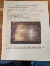
On this amplifier, the capacitor leads went around the board edges. The new parts are smaller, so I drilled holes, neatly lined up as if designed that way. This saves you lead length, which you'll need to do. It makes the new parts sit properly and look one heck of a lot neater.

Power supply capacitors have voltage across them, leakage isn't as important (important point). High frequency performance is important. There is lead length between those and the circuit, so don't go nuts bypassing them (in other words, don't bother), it is a waste and makes a mess inside the unit. Coupling capacitors must have low leakage, high frequency performance isn't very important. Amplifiers only respond so high in frequency and any decent capacitor will greatly exceed the need. Do not bypass coupling capacitors! Tube power amplifiers rarely have useable response above 200 KHz. You won't hear above 30 KHz if you were a kid, never mind middle aged!

Read data sheets, use common sense and be aware what the part does. If you do that, you'll be fine. If the part is physically too large, you can't use it. Do not increase filter capacitor size very much, that creates problems. In short, ignore most of what you read on the internet.

Also. If industry doesn't use a part, audio people don't get it. "Audiophile approved" parts are most often inferior to good industrial ones. Hand wound anything is not as good as machine wound (sorry folks). Capacitors do not have to burn in. Sure, capacitors and resistors shift value slightly, but you will never hear it. If you could, missiles would strike the wrong target and we would have missed the moon. Some parts are inexpensive because they are made in massive quantities. A 1N400x diode is highly engineered, buy from a good manufacturer though. Other parts are expensive due to low production, and their use is for another purpose entirely (fast recovery diodes is a great example). Using the wrong part for an application will not yield better performance and often creates problems.

Those are the basics.
 
Hi Dennis,
Carbon composition resistors and the old impregnated paper capacitors aren't very good. But that is all they had back then. If you use good components available today, you can't help but have improved sound quality (lower distortion & noise).

What you need to do is remember what each component does. Replacements should be better suited for those circuit positions. You'll have to increase the wattage rating of resistors simply to get the breakdown voltages you need. It also helps the leads are longer! Always place the new part where the old one was as closely as you can.

On this amplifier, the capacitor leads went around the board edges. The new parts are smaller, so I drilled holes, neatly lined up as if designed that way. This saves you lead length, which you'll need to do. It makes the new parts sit properly and look one heck of a lot neater.

Power supply capacitors have voltage across them, leakage isn't as important (important point). High frequency performance is important. There is lead length between those and the circuit, so don't go nuts bypassing them (in other words, don't bother), it is a waste and makes a mess inside the unit. Coupling capacitors must have low leakage, high frequency performance isn't very important. Amplifiers only respond so high in frequency and any decent capacitor will greatly exceed the need. Do not bypass coupling capacitors! Tube power amplifiers rarely have useable response above 200 KHz. You won't hear above 30 KHz if you were a kid, never mind middle aged!

Read data sheets, use common sense and be aware what the part does. If you do that, you'll be fine. If the part is physically too large, you can't use it. Do not increase filter capacitor size very much, that creates problems. In short, ignore most of what you read on the internet.

Also. If industry doesn't use a part, audio people don't get it. "Audiophile approved" parts are most often inferior to good industrial ones. Hand wound anything is not as good as machine wound (sorry folks). Capacitors do not have to burn in. Sure, capacitors and resistors shift value slightly, but you will never hear it. If you could, missiles would strike the wrong target and we would have missed the moon. Some parts are inexpensive because they are made in massive quantities. A 1N400x diode is highly engineered, buy from a good manufacturer though. Other parts are expensive due to low production, and their use is for another purpose entirely (fast recovery diodes is a great example). Using the wrong part for an application will not yield better performance and often creates problems.

Those are the basics.
I have just found McShane's web page. Can't quit figure out how to actually order his kits but that seems the way to go.
 
I didn't use those kits for a reason. But, it's better if you're not sure I guess.

One thing I really didn't like was the cap board changes the way the grounds run.
 
I didn't use those kits for a reason. But, it's better if you're not sure I guess.

One thing I really didn't like was the cap board changes the way the grounds run.
I feel competent to replace capacitors and resistors 1 for 1. It helps to have a schematic and a picture of installed components, which the simple things I've done have had. Making modifications is a bit different. I'd kind of need detailed instructions. It looks like several AK inmates have been happy with those kits.

But I'm willing to listen to alternatives. This is a nice amp and, in its current state, the most expensive I've had. It would be nice to get it right.
 
Look at it this way. Seasoned, trained engineers designed that amplifier. The wiring was an integral part of the design. Change what they did at your peril.

I've designed PCB replacement boards, some for regulators, some for capacitors. For capacitors, I learned you keep everything as close to original as possible. Make it mechanically secure, make the wires end up about where they originally did. Pay very close attention to how the ground currents run. It is so easy to make things worse trying for an easier or cheaper alternative to a can capacitor.

When I rebuild my own, personal amplifiers, I use CE Manufacturing can capacitors. I do the same for my clients. They get the best job I know how to do because it is their money I am spending. One irreplaceable thing you are committing (and me) when you work is your time. This has higher value than the higher cost of the right parts and techniques. Imagine having to redo a job.

When I was apprenticed, doing it right was drilled into my head. This also means lead dress and component replacement. You remove the solder and old leads from the terminals, and install the new component in the same manner. The highest compliment you can be given is that it doesn't look like anyone has been there. Sloppy workmanship means poor work.
 
Look at it this way. Seasoned, trained engineers designed that amplifier. The wiring was an integral part of the design. Change what they did at your peril.

I've designed PCB replacement boards, some for regulators, some for capacitors. For capacitors, I learned you keep everything as close to original as possible. Make it mechanically secure, make the wires end up about where they originally did. Pay very close attention to how the ground currents run. It is so easy to make things worse trying for an easier or cheaper alternative to a can capacitor.

When I rebuild my own, personal amplifiers, I use CE Manufacturing can capacitors. I do the same for my clients. They get the best job I know how to do because it is their money I am spending. One irreplaceable thing you are committing (and me) when you work is your time. This has higher value than the higher cost of the right parts and techniques. Imagine having to redo a job.

When I was apprenticed, doing it right was drilled into my head. This also means lead dress and component replacement. You remove the solder and old leads from the terminals, and install the new component in the same manner. The highest compliment you can be given is that it doesn't look like anyone has been there. Sloppy workmanship means poor work.
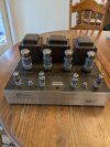
PXL_20260925_162305829.jpg It is here. I did get a response from McShane. He will sell the kits but he points out that they are for experienced techs as one would be putting new components in new places. I tend to agree with you and I had been looking at CE can capacitors. They do not have what I need for my little Pilot.

First problem, the schematic I have is such poor resolution that I can't read anything on it. To do any work on this, it would be nice to have legible schematics with a parts list. (Edit) I do have color schematics.

It came with SovTek 5881 tubes as a lower power option for testing but I hadn't intended to try turning it on. I believe one should at least replace the power electrolytics first. However, since it was powered up to check the transformers, could the old electrolytics have reformed? I'm probably high lighting just how limited my experience is but I remember some people power these gradually with adjustable power supplies.

Anyway, I will have to look under the hood to see what it looks like. Maybe I can get CE capacitors coming while I try to find a better schematic. Someone here should have something. (Edit) CE doesn't have a 500 V 90/30/30. In fact, they don't have a 90 mF at all.
 
Last edited:
Reforming capacitors is done in two ways. Gradual increases in AC power using a Variac. Using a current limited power supply (or current source) to reform. I use an HP 6186C to do this.
The important thing is to limit the heat generated in reforming. If you damage the capacitor, that's it. Done. You need to be patient as this is a chemical reaction, forming the oxide layer back on the elements. Using an external DC supply allows me to measure the leakage current and know where it is. I don't expect you to have that, but you can measure voltage drop across a resistor to determine current.

The capacitors will not be the same values exactly. The two capacitors after the doubler can be quad 40uF @ 525VDC. Just combine the sections. I designed a PCB so I could use snap type capacitors for the doubler for my service, it also has large PCB terminals for original wiring. It mounts exactly the same as the original capacitors. Otherwise use something close in an FP mount, you can use a double section to make up the values (or whatever adds up to the approximate capacitance you need). In general, do not increase capacitance greatly.

PM me and I'll try to help.
 
Reforming capacitors is done in two ways. Gradual increases in AC power using a Variac. Using a current limited power supply (or current source) to reform. I use an HP 6186C to do this.
The important thing is to limit the heat generated in reforming. If you damage the capacitor, that's it. Done. You need to be patient as this is a chemical reaction, forming the oxide layer back on the elements. Using an external DC supply allows me to measure the leakage current and know where it is. I don't expect you to have that, but you can measure voltage drop across a resistor to determine current.

The capacitors will not be the same values exactly. The two capacitors after the doubler can be quad 40uF @ 525VDC. Just combine the sections. I designed a PCB so I could use snap type capacitors for the doubler for my service, it also has large PCB terminals for original wiring. It mounts exactly the same as the original capacitors. Otherwise use something close in an FP mount, you can use a double section to make up the values (or whatever adds up to the approximate capacitance you need). In general, do not increase capacitance greatly.

PM me and I'll try to help.
That makes sense. The amp came with a report from the engineer the seller used to check it. It sounds like he wouldn't replace all caps and resistors but the electrolytic cans need to go.


Engr report pg 1.jpgEngr report pg 2.jpgEngr report pg 3.jpg
 
Hitting the amplifier with 100 VAC would be unwise. The electrolytic cans need to reform by controlling current.

The coupling capacitors and bypass capacitors should absolutely be replaced with proper axial lead types. Don't use radials like some folks do (radial film caps like "orange drops" for example).

I have the advantage of having some really good LCR meters, like HP 4263A and 4192A, plus a few others. I can disconnect a capacitor and get an accurate read on health by observing the capacitance, and DA (not ESR). Capacitors in high stress areas, like the voltage doubler, are on the replacement list. The direct first filter also sees a lot of stress (peak currents). If there is reasonable resistance in series, it lives an easier life - but at least check them disconnected.

Check resistors. Wirewound types will probably be okay unless overheated. Carbon types are often way out of tolerance. If you have to remove a resistor when changing power supply capacitors, just get new resistors. Remove leads from terminals, don't snip and tack the new part in. That is total hack work. To preserve the terminals, you can destroy the component to make it easier. The valuable things are terminals and circuit boards, not usually the part.
 
Hitting the amplifier with 100 VAC would be unwise. The electrolytic cans need to reform by controlling current.

The coupling capacitors and bypass capacitors should absolutely be replaced with proper axial lead types. Don't use radials like some folks do (radial film caps like "orange drops" for example).

I have the advantage of having some really good LCR meters, like HP 4263A and 4192A, plus a few others. I can disconnect a capacitor and get an accurate read on health by observing the capacitance, and DA (not ESR). Capacitors in high stress areas, like the voltage doubler, are on the replacement list. The direct first filter also sees a lot of stress (peak currents). If there is reasonable resistance in series, it lives an easier life - but at least check them disconnected.

Check resistors. Wirewound types will probably be okay unless overheated. Carbon types are often way out of tolerance. If you have to remove a resistor when changing power supply capacitors, just get new resistors. Remove leads from terminals, don't snip and tack the new part in. That is total hack work. To preserve the terminals, you can destroy the component to make it easier. The valuable things are terminals and circuit boards, not usually the part.
Is any current production resistor good or should I be looking for specific types?
 
Look at your supplier of choice. I normally use Metal Oxide for power supply areas that may have surge currents. Metal film for most other things. Heavier current surges or higher temperatures get wire wound (these are inductive). Inductance is sometimes a good thing, sometimes the last thing you want!

Look up the data sheet to determine overall length including leads - is it long enough? Then look at the rated voltages. Good metal film, 0.6W types are typically 350V maximum, but may be lower (down to 75V !). I have to buy units rated for 2.5 or 3 KV, sometimes 6 KV depending on what they have in stock. On top of this, look at resistance variation compared to both temperature and applied voltage.

Common sense stuff that no one thinks about.
 
Back
Top Bottom