• The move to the new server is done. There are some software and database maintenance updates in process. This has us passing the hat around to help out. We appreciate any donations. Seriously, even a dollar helps. The payment page may be found here - https://www.audiokarma.org/support.html

The Technics SA-R477 late 80s restoration project

skyegreen424

brandon
Hi!!

I posted in another thread to gauge interest in logging the recap of a late 80s Technics SA-R477 100wpc unit.

Here's the thread because I made a parts list, checked it twice, and ordered it all on Digikey for delivery in about three days.

I've got a healthy mix of electrolytic capacitors and polypropylenes. There's about 20 3.3uF capacitors all through the receiver and all of those will be "upgraded" to polypropylenes.

Anyways, here's what I've done so far:

I cleaned the potentiometers.

I also replaced the relay. This was a more involved repair than cleaning the pots but it needed to happen. Last year I tried cleaning the original relay myself but in the process destroyed it. A year later with a years worth of learning and hindsight and I would have and should have just put a new relay in. I've got a new clear Omron relay installed and it looks awesome. I made a TikTok of the process if anyone wants to check it out -- https://www.tiktok.com/@dead__fi/video/7122649932762467630?_t=8ULP2SdW3Xm&_r=1

Also, I'd like to say that this is a super easy unit to work on!! It's got a lot of parts sure but there's a lot of the same cap PLUS you can take the entire boards out easily. Maybe I just haven't worked on nicer units before but this is so much more convenient than constantly turning the entire unit to get one cap out. Good stuff, Panasonic!

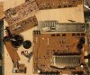
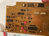
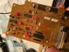
I'll attach some pictures I've taken of my process so far. I gotta get more into the habit of doing this, cus I go to an art school which is all about documenting your practices/steps to completion, haha.
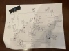
tempImageDmfQyt.png tempImagedmpSoU.png IMG_0048.jpg

Anyways, I've got a few questions.

1) Why did they use such tiny capacitors when the boards support and even seem to be designed for the larger/more normally sized equivalents? Is there some kind of performance benefit or is this to decrease the cost?
2) I'm aware this unit runs hot even though it's got a fan in it. Does putting in an always running fan actually help this series of units? I've seen a couple tutorials for how to add in a constant fan plus its controller but if anyone knows any good tutorials for how to install a better fan let me know :-D
3) Should I replace the thermal grease currently on the transistors with something better like computer thermal paste (I have arctic mx4 which I believe is not conductive)
4) Any best practices for recapping besides using a dim bulb tester and testing the unit constantly that I should be aware of?

Thanks guys!!! Hope this log is helpful somewhat to somebody. There are many great amplifiers from this time period which are approaching the age where a recap as a preventative thing will allow its use for many more years... that's the big reason why I'm in deep on this one ;_)
 
Register to hide this ad
It’s too late now, but I wouldn’t have disassembled it completely. I usually work on a board and test after it’s completed. Makes it easier to find any errors or damage caused by me.

if the thermal paste is dry and kind of crumbly, I would replace with sil-pads or the Arctic paste would be fine.
Best practices…don’t put tools or small parts on the shelf just above your work area. I dropped a needle nose plier into a receiver as I was finishing the alignment.
Change one part at a time. Don’t trust the silk screen on the board for polarity. Take pictures of everything before you take it apart. Take several shots of each board so that you can identify the polarity Or orientation of the components in case you pull something and didn’t check first. This is especially helpful if there are wire jumpers between boards sometimes you have to remove them or the connections break. Don’t be afraid to brick it. With that said, don’t just turn coils and pots to see if it improves anything. Follow service manual procedures unless you are familiar with a different method. Take your time and if you drop a needle nose plier into it, walk away for a day or so and come back with a fresh mind. Good luck and post more pics. These kind of threads are some of my favorites.
 
The fan in my R530 quit after about 2 years from purchase. Opened it up and determined the supply was gone. Found another 12V on the board and ran it off that. Screwed up the surround, but I could live with that.
Just recently the fan itself started to go so I undid the "fix" and installed a computer fan using a wall wart plugged into the switched outlet on the back.
While I was looking at fans for that I noticed they also have a variety of low noise/ low profile fans designed to sit on top of a unit.

My heat compound is still good so I didn't mess with it. Is that heat compound you mentioned the carbon nano tube stuff? That is non-conductive. I bought some for an amp but put some on my computer processor to see how it worked and it dropped the temps by 10C.
 
The fan in my R530 quit after about 2 years from purchase. Opened it up and determined the supply was gone. Found another 12V on the board and ran it off that. Screwed up the surround, but I could live with that.
Just recently the fan itself started to go so I undid the "fix" and installed a computer fan using a wall wart plugged into the switched outlet on the back.


This often is caused by the bearings drying out… makes fan motor work harder and it wants more current to run, which knocks off the driving transistor(s)
 
This often is caused by the bearings drying out… makes fan motor work harder and it wants more current to run, which knocks off the driving transistor(s)
Except the fan ran fine for the next 25 or so years, so probably not that.
 
Tiny capacitors are a result of good design -- if the rating is correct and the voltages are good for the circuit, size means nothing at all. Note that ALL low uF (3.3uF and below) are rated at 50V no matter where they are in a circuit (unless the voltage is actually higher). This is simply because making them at lower voltage ratings becomes difficult due to the very small size.

All modern electrolyitc caps are smaller than the same ratings caps from the 80's, quite a few advances in the science of making electrolytic caps since then. They last a lot longer, too.

As far as re-capping goes, I'd stick pretty close to what was in there unless you have a calculated improvement in mind. Capacitor choices in electronics are not determined by someone in the accounting department, the value was chosen by the design engineers to perform some specific function and the voltages are determined by the circuit. Upping the voltage is OK, using film instead of small value electrolyitcs is fine -- those were actually a cost savings at the time, as film equivalents were uncommon, very large, and expensive. Be aware that not every electrolytic can be swapped to a film, in some cases some characteristic of the electrolytic is necessary.

Bigger is not better in capacitors, calculate the results of any changes and make sure they will not affect operation or frequency response before making substitutions in uF value. Do not use huge film caps with long leads either -- they make an excellent AM antenna, usually in some part of the circuit where it will get into the signal....
 
Tiny capacitors are a result of good design -- if the rating is correct and the voltages are good for the circuit, size means nothing at all. Note that ALL low uF (3.3uF and below) are rated at 50V no matter where they are in a circuit (unless the voltage is actually higher). This is simply because making them at lower voltage ratings becomes difficult due to the very small size.

All modern electrolyitc caps are smaller than the same ratings caps from the 80's, quite a few advances in the science of making electrolytic caps since then. They last a lot longer, too.

As far as re-capping goes, I'd stick pretty close to what was in there unless you have a calculated improvement in mind. Capacitor choices in electronics are not determined by someone in the accounting department, the value was chosen by the design engineers to perform some specific function and the voltages are determined by the circuit. Upping the voltage is OK, using film instead of small value electrolyitcs is fine -- those were actually a cost savings at the time, as film equivalents were uncommon, very large, and expensive. Be aware that not every electrolytic can be swapped to a film, in some cases some characteristic of the electrolytic is necessary.

Bigger is not better in capacitors, calculate the results of any changes and make sure they will not affect operation or frequency response before making substitutions in uF value. Do not use huge film caps with long leads either -- they make an excellent AM antenna, usually in some part of the circuit where it will get into the signal....
I didn't know that about the low uF capacitors. Interestingly, this unit has a myriad of 3.3uF 25V capacitors which I am replacing with 3.3uF wima films which fit perfectly in the place of their tiny predecessors. So far, I've only recapped the front display board, but that board also houses the graphic equalizer and suffice to say that's all working great now even though I've upped the voltage of those caps. I think in my experience doubling the voltage is fine. Seems to be just fine here. There must have been a reason as to why the designers chose such small capacitors, and I wish I could find out more since I've never heard of a deliberate use of tiny electrolytic caps. I'd also assume that films are much better than electrolytic for the most part (I know their inherent bipolarity can cause issues in some circuits) but to be honest I tried to stay as close to the original unit as possible since this is a relatively unusual recap of a poorly archived model of Technics receiver. I did not want to deal with any pieces that would not fit so I only used films for values 3.3uF and below.
 
Cool!! Some of the labor is beginning to pay off :_)

I'm gonna try to do this as slowly and as meticulously as possible so I don't get anxious about screwing something up. I've been taking a lot of photos of the process which has been helping me quite a bit. I know this isn't the best method of checking your work, but it brings peace of mind for me because there are so many capacitors to replace without a service manual (if anyone has any leads on a SM for this unit it would be greatly appreciated!!)

First section done: Today I focused on the display board. I reattached the VFD and all the shielding and hooked everything back up for a brief test on the DBT and everything seems to be working (I needed a higher wattage bulb to get the relay to click)
After listening through the headphone jack for a bit and double checking that the DC offset was correct I decided to plug the thing into full power. The fruits of my labor have manifested in the form of a much brighter VFD than I had observed before. I was a bit surprised but I'm glad it's as nice and bright as it is now. I could stop here and it would be like an all new unit. I know I'm waxing poetic a bit but it is brighter. Woohoo!

I also followed this with a recap of the graphic equalizer section. This went perfectly fine too. I'm attaching a few photos so enjoy if this is the kind of thing you like. tempImaget03K3U.png
tempImagegnPYaD.png tempImage9NxkGc.png

For anyone who tries to do something like this in the future I have to say that this was pretty difficult because you have to detach the VFD from the display board to get to the capacitors underneath it. It's not easy to reattach the display so take your time. Also make sure you have a good properly temperature controlled soldering iron or else you risk destroying the PCB traces. Yikes !! I just got a Hakko which I really like using. I had a Yihua soldering station for about a year and that thing was garbage .... I would not take on this kind of project with a crappy non temp controlled soldering iron in my opinion. I have done a Sega Gamegear before with a plug in iron and it worked afterwards so there are exceptions, but it's not really worth the risk :-/
 
I know I was gonna be patient but. Woohoo. Glad I get to listen to this for next few weeks :0)

I know it's subjective but yeah a recap is **subjectively** a night and day difference on this unit. Photos and stuff I've learned to come
 
Back
Top Bottom