• Please note that Audiokarma will be offline briefly for updates early on Monday morning, September 28th.

Thinking of getting into my G-5700

ossodiseppia

Well-Known Member
Last summer, I bought a banged up G-5700 to play with. I thought it would be something fun to cut my teeth on. I'd really like to do a pretty complete tear down in order to learn as much as I can. I don't have but a few bucks in it, so if I destroy it, there will be little financial hardship. And, it's not rare, so...

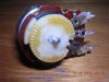
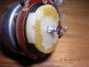
I'd like to know how folks disassemble the pots so that they can be put back together after cleaning.
 

Attachments

  • DSCN0396.jpg
    DSCN0396.jpg
    78.6 KB · Views: 60
  • DSCN0397.jpg
    DSCN0397.jpg
    63.4 KB · Views: 47
  • DSCN0398.jpg
    DSCN0398.jpg
    100.6 KB · Views: 60
Register to hide this ad
This looks interesting!

I wouldn't think that further disassembly was necessary. Aren't there openings in the side opposite the white geared disk where cleaner can be sprayed in?
.
 
If cleaning doesn't fix a pot like that the guy to talk to is Kale.
He has posted some fine work on such things, but remember, they are NOT intended to be disassembled.:no:
 
I m aware they are not. I've seen Kale's posts and I seem to remember that he disassembled one or two pots. Or, was it just the push and selector switches??
 
As I recall from the test drive some months ago, the sound was very garbbly in one channel and one of those wonderful LEDs wasn't working.

I suppose I'll clean the pots and switches and give it another try before tearing it up.

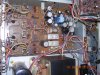
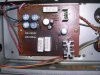
Here are some pics of the boards. First up is the Power Supply Board. It looks to have gotten a little toasty in the past. It looks like a few resistors and one or both transistors were replaced.

attachment.php


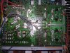
The Power Amp board looks like it's been "worked on".

attachment.php


attachment.php


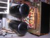
And lastly, the two large caps for the power supply look a little puffy. I just may be the plastic, because I can push on it.

attachment.php
 

Attachments

  • DSCN0404.jpg
    DSCN0404.jpg
    86.6 KB · Views: 158
  • DSCN0403.jpg
    DSCN0403.jpg
    132.2 KB · Views: 156
  • DSCN0399.jpg
    DSCN0399.jpg
    147.3 KB · Views: 155
  • DSCN0400.jpg
    DSCN0400.jpg
    105 KB · Views: 156
Disassembling and restoring those pots are post-graduate work in the electronics hobby. And you have to have exceptional hand coordination and patience IMHO.

Use de-oxit three times; if it's not working then, replace it with a $12.99 Noble. The inexpensive Elna's for Audio off of eBay would replace the large caps if it were my project. Best to you.
 
Last edited:
Disassembling and restoring those pots are post-graduate work in the electronics hobby. And you have to have exceptional hand coordination and patience IMHO.

I understand. the point of working on this unit is to develop those skills. I have a Pioneer SX-450 that I would like to do the same thing with. If I am comfortable with the work that I do on these two units, then I will move up to the G-7000, G-801, G-8000 and end up on the G-22000. I would like to recap all of these and do a through cleaning job. The goal is to develop skills so that I can do a proper restoration on the G-22000, before I get too old and go deaf. :yes:

That is the Digital Powersupply Brian, it does the silly digital tuning circuit and that Fluro display.....it runs pretty hot, I would consider replacing the regulator on that board (the TO-220 transistor).

Thanks, Kevin. I was considering doing both transistors and the caps when the time comes. Is there anything that can be done to help cool the transistors? Maybe something like a bigger heat sink?
 
Thanks, Kevin. I was considering doing both transistors and the caps when the time comes. Is there anything that can be done to help cool the transistors? Maybe something like a bigger heat sink?

Most of the heat comes from those two 5watt 330Ω resistors, and because the board is upside down, the heat rises and scorches the board....

I think the transistors will be OK if you replace them, they have sufficient heat sinks on them....
Maybe replace those resistors and stand them up off the board more than they are now.....its about all you can do, all the GX7000 series I have ever seen look like this.....

I will be watching and give advice where I can......off to a good start....:thmbsp:
 
Thanks, Kevin. I think you have a great idea to pull those resistors away from the board. Hopefully that will help keep some of the heat from baking the board.

This project will progress very slowly.
 
I purchased a 20amp VARIAC for almost half the going rate. I've yet to plug it in and test it. This brings me a bit close to starting on my projects.

attachment.php
 

Attachments

  • DSCN0408.jpg
    DSCN0408.jpg
    56.1 KB · Views: 133
I said this was going to be slow....

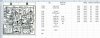
Ok, so I'm going to make a spreadsheet for each circuit board so that I can keep track of what goes where. I've started with the F2916 board because it's small.

attachment.php


Spreadsheet


attachment.php


F-2916 board


attachment.php


attachment.php


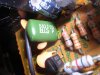
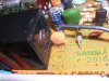
In the two pictures above, I need a little help identifying the kinds of caps these are so that I can order the right ones.

attachment.php


This board has two transistors, when I search for them by what's printed on the side, I'm a bit overwhelmed with choices. I don't have any idea which to choose, other than the one that is "In Stock".

I am very much a rookie at this, but would like to learn and not just be fed the information. Thank you.
 

Attachments

  • DSCN0419.jpg
    DSCN0419.jpg
    78.1 KB · Views: 125
  • DSCN0418.jpg
    DSCN0418.jpg
    80.5 KB · Views: 124
  • DSCN0422.jpg
    DSCN0422.jpg
    92.5 KB · Views: 125
  • reads.jpg
    reads.jpg
    60 KB · Views: 127
  • transistors.jpg
    transistors.jpg
    76.9 KB · Views: 128
The green one is C605, 0.068µƒ, Mylar. Find it on the "X-Ray" (your first pic, or page 9 of SM) and identify the other components it is tied to, like TR602/B. Now find it on the schematic on page 13 to get the value and any identifying marks. The key (lower left corner) identifies the small circle in a circle as Mylar. Read the schematic carefully - it looks like the mylar symbol is associated with C604, which cannot be because that is clearly an electrolytic.

I am confused about the other one. The 103 in your pic identifies it as 0.01µƒ, but the schematic says C601 should be 33pƒ. The "X-Ray" also shows R601 and R602, which are also in the schematic, but clearly NOT on your board. They should be where the 'circled' B is in your pic. I'll defer to Kev here, but I'd suggest you go with the board as Sansui is well known for not updating their service manuals and schematics.

Transistors: My suggestion is to start with data sheets for the 'originals' so that you are familiar with the specs. www.alltransistors.com has been a good source of information for me. Go to their main page and enter the full TR name (2SC1845) in the search window - it will return a list of all the versions in its database. Click on the one you want and the next page will give you info on that TR, links to datasheets available, and a link to "Equivalent Transistors". Click on that and you get TR info in a spreadsheet format. You can hilite what you want, copy that, and paste it in your own spreadsheet, then correct the formatting. Look for TRs with about the same, or better, specs than your originals.

Also do a Google search on AK ("site:AudioKarma.org 2SC1845") to see if any posts have suggestions for suitable subs. Markthefixer has done a lot of research on this.

Now you can look at places like Mouser, Digikey, MCM Electronics, On-Semi, or others, to get availability and prices. Think about the fact that S&H charges can mount up quickly, so you might want to hold your orders until you have larger numbers of items. I decided to just wholesale replace TRs Caps & Resistors in the Audio side of the main board in my G-4700s and G-6700, so I made some large orders.

I think this will be post #999 for me, so the next one will be a big deal (haha).

Goog Luck - - -
.

 
Hey thanks for the reply. I did a little research this morning and found a nice write up on capacitors. So. I've got that to read over

I'm actually not paying that much attention to the schematic. The reason being is that the SM covers three models, G-5700, G-6700, and G-7700. I suspect the schematic pertains only to the G-7700. So, I think it's prudent to pull the info directly from the board. Besides, I've been told there are lots of ommissions and mistakes in the manuals. The values on my spreadsheet are from the board, not the schematic.

I plan to go thru each board and make an inventory before I order. My preference is to place an order for everything I need for this unit.
 
If cleaning doesn't fix a pot like that the guy to talk to is Kale.
He has posted some fine work on such things, but remember, they are NOT intended to be disassembled.:no:

Sorry for late answer, I just found that, so I decided to answer...
I agree with you nosirrah, volume potentiometers are not intended to be disassembled... but if you, for some reason must to disassemble it, you should be very, very careful!! If you make a mistake, probably you will destroy the potentiometer.
Here, it is my new example... now currently I am working on one AUX1 amplifier, and I just cleaned one ALPS Black Beauty volume potentiometer, so the biggest problem is how to remove Push Nut from axle of potentiometer.

I solve that problem by buying new similar push nuts...

PICT1177_zps85d5f3f5.jpg


left is old Alps genuine Push Nut, and right is new one

here, you can see all parts of ALPS volume potentiometer

PICT1176_zpse12993ed.jpg


and, here you can see new Push Nut on its place

PICT1178_zps8ed8d42d.jpg
 
Ok, that's one of the sealed units, much like what's in the G-22000/G-33000. But the ones I am looking at in the smaller G units, don't have the push nut, like yours.
 
Thanks for the link. I finally cleaned the pots a bit and powered it up. The left channel is really distorted. I turned all of the pots to see if they were sratchy and possibly casuing the issue, but they were not.

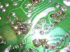
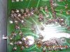
I got an optivisor and had a nice look at the traces on the power amp board. It looks like someone with much less experience than me hacked on it pretty good. Something on the other side of the hacked traces is probalby casuing the intermitant distortion.

attachment.php


attachment.php


There is good news, the LED meters work. So, that means that hard to find chip is working.

attachment.php
 

Attachments

  • DSCN0432.jpg
    DSCN0432.jpg
    64.1 KB · Views: 81
  • DSCN0434.jpg
    DSCN0434.jpg
    131.6 KB · Views: 82
  • DSCN0435.jpg
    DSCN0435.jpg
    145 KB · Views: 83
Back
Top Bottom