You've just posted a tutorial for boosting performance of an SA-101!

Now to find where I stashed mine ...
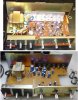
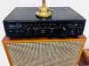
Here's more, and applies to all of the mini amps that don't employ chips or driver interstage transformers:
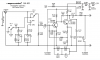
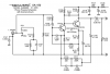
The circuit is very similar in all of them. The SA-10 is the simplest, having only a voltage amplifier in front of the power amp. But in all of them, bandwidth is curtailed on the bottom end due to distortion that otherwise arises. That distortion is caused by small electrolytic caps (two in particular); partly a cost issue and probably also a method of getting the amp to seem like it has more power since the bass is where the energy is, and smaller amps like this are often on smaller speakers.
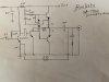
The first electrolytic to be questioned is the input coupling cap. The formula for calculating its cutoff frequency is f= Rx C x 6.28/1,000,000 People who are familiar with this formula will have noticed that usually the divider is 1, but here its a million so that the actual cap value in uf and the resistor value in ohms can result in Hertz. Essentially the input bias network values are in parallel since they go to ground or Vcc+ which has a low impedance with respect to ground. We can see right away that this cap is rolling far too high; I recommend setting it about 4x lower. I've ignored the impedance of the base of the transistor BTW in the above formula. This isn't rocket science; I just need to be able to measure and hear improvement with real bass.
The second cap is in the emitter circuit of the input transistor to the power amp- its an emitter bypass cap. Its low end timing constant means that anything below that frequency is rolled off. Now if you simply put in a bigger output coupling cap, the result will be that there is less feedback below the cutoff of that emitter bypass cap, so the amp makes more distortion. On top of that, the coupling cap to the base of the top output transistor has a timing constant too. If the amp is seeing frequencies below the cutoff, the output waveform will be asymmetrical! Now the amp won't see any of these frequencies unless either the caps in question start to fail,
or if you install bigger values at the input and output of the amp.
But it would be nice if the amp made more bass- especially in the case of the SA-10, if you're running a desktop. So you have to replace all five electrolytics in the power amp section. The output coupling cap should be 2200uf if you really want a proper timing constant with relation to an 8 ohm load. That puts the -3dB point at about 9Hz which is still a little high, but it will mean less phase shift over much of the audio band so the amp will be more 3D. In the case of the SA-10, this means that all the caps have to increase in value by about 10:1. In the cases of the other amps its more like 4:1.
Also, to me the amps tend to sound a bit dull with digital sources. This is not due to bandwidth, as all of these amps have bandwidth to 60KHz and beyond. Its due to the loudness contour. I don't like loudness contours because they are really hard to get right- there will be only one input level, one speaker efficiency and one distance from the speaker in a room of the right liveliness for the contour to be correct! So I pull the loudness parts out (a cap and resistor tied to the tap on the volume control). This gives the amp more gain and greater liveliness without being bright.
Now there is one spot in the circuit that I'm a bit curious about. The input voltage amplifier to the power amp is the transistor (usually a 2SC373 or the like) with the emitter bypass cap. Its biased on, but the bias circuit provides no feedback. The issue is that when you look at its output it can be quite distorted; its output is a composite of the input signal and the feedback correction. So it makes sense (to me, anyway) that this stage needs to be low distortion on its own. So instead of the existing bias network, I'm thinking to pull out the network and replace it with a single feedback resistor from the collector, which is set to provide the base with the correct current. In the case of the SA-10, SA-101 and SA102, this value would be 100K with the regular bias network removed. I suspect the designer didn't do this on account of the circuit needing gain, but with the increase in gain from no loudness contour, this seems like it should work just fine. I've not tried this bit yet but plan to very soon.