• The move to the new server is done. There are some software and database maintenance updates in process. This has us passing the hat around to help out. We appreciate any donations. Seriously, even a dollar helps. The payment page may be found here - https://www.audiokarma.org/support.html

Time to winnow down the speakers. Cornwalls? Valencias? 605A's?

Small world. Clarkston and West Bloomfield don't have a tight, tree-lined roadracing track though. I like Waterford. I spend a lot of time stomping around Bald Mountain park in the summer, but that and concerts at The Palace are the only times I go North these days.

(snip)....

If you're referring to the Waterford Hills track/Oakland County Sportsman Club, it's actually in Independence Twp. (as is the village of Clockston) although it's on the border of Waterford. Physically, the mound of dirt that is "Waterford Hill" is also in Independence Twp. Within the Clockston/Independence community there has been idle talk of renaming Waterford Hill to Clarkston Hill such is the cachet of Clockston. But I digress. Back to the subject at hand.
 
Steve:
My tech ref is : STANDARD HANDBOOK FOR ELECTRICAL ENGINEERS 12th (>10) EDITION (1987) Edited by DONALD FINK. Chapter 2, FILTERS. It also quotes the work of ZOBEL in 1923. I use a filter source Z= 0 and load Z= 13.
To find the delay required, use the pulse and pickup the acoustical signal with an omni mic 12" on axis of the Duplex. Measure the time on a oscope or Mac/PC and software.
Re the web : all I did was use the Mac Web setup. Sorry I can't help how it came out
Don.

Thanks:

I'll be looking that one up.
 
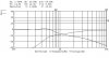
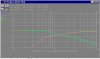
605A/N1600C Frequency Response & Voltage Drive

Courtesy Donald Patten:
 

Attachments

  • 405FREQN1600REF COLORb.jpg
    405FREQN1600REF COLORb.jpg
    46.2 KB · Views: 30
  • 605_N1600C XO curvesa.jpg
    605_N1600C XO curvesa.jpg
    34 KB · Views: 34
ZILCH
Thank you for the help in posting these images.

The Left image : in red, the input signal to the N1600C using a FFT signal.
in green , the acoustic signal 12" on axis with an omni electret microphone.
The right : in green, the N1600C signal to the 15" woofer
in red, the signal to the HF driver. These curves were made with the speaker connected as the XO load.
Both signals are processed with a Mac and F.A.S.T. software
Don
 
Courtesy Donald Patten:

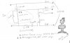
so Don, This is the 'stock' N1600C crossover voltage drive. Is this made with the values shown in the earlier N1600C schematic diagram posted (R's are 20 Ohms, 5 Ohms and 25 variable, C's are 16uf and 4uf, L is 1mh?

I'm asking because in my N1600C crossovers I actually found the 5 Ohm in the drawing to be a 4 Ohm and the 4 uf in the drawing to be a 5uf.

Also, I measured the iron core inductor at 1mh but now I'm doubting that measurement. I measured a number of chokes today. The aircores all measured within +0 to -5% of the marked values. The iron cores measured lower than the marked values, which is odd, sometimes by 30% low.

I've listened to these speakers for about 15 hours since changing the crossover to the version shown, since it's easier to draw than describe. It sounds like there's a suckout in the presence region or a little lower. Like it lacks fullness below about 1500 Hz. That would seem to indicate maybe a falloff in response at the top of the woofer's range. I haven't tried any 'instrumented' testing yet, preferring to get impressions of the sound first before the SLM starts making me think I hear things I don't.
 

Attachments

  • Image3.jpg
    Image3.jpg
    35.1 KB · Views: 27
I'm doing sims here trying to replicate the voltage drives.

The 12 Ohms certainly lowers the "Q" of the lowpass substantially; the bump at 1 kHz is gone. At 20 Ohms, its flat. With no R there, it's more like Don's voltage drive, +2.5 dB. I suspect that resistor is creating the notch in the response you're hearing.

Help me, now, Le for a typical compression driver is what?

And in the sim, that should be in series with the driver R for a more accurate driver model, correct?

If somebody could measure the actual driver impedances at 1.6 kHz, that'd be REALLY helpful.

I cannot get the 10 dB of HF compensation shown in Don's voltage drive out of this circuit. :dunno:
 
I'm doing sims here trying to replicate the voltage drives.

The 12 Ohms certainly lowers the "Q" of the lowpass substantially; the bump at 1 kHz is gone. At 20 Ohms, its flat. With no R there, it's more like Don's voltage drive, +2.5 dB. I suspect that resistor is creating the notch in the response you're hearing.

Help me, now, Le for a typical compression driver is what?

And in the sim, that should be in series with the driver R for a more accurate driver model, correct?

If somebody could measure the actual driver impedances at 1.6 kHz, that'd be REALLY helpful.

I cannot get the 10 dB of HF compensation shown in Don's voltage drive out of this circuit. :dunno:

The HF compensation depends on the setting of the pot. With the wiper all the way at the 'top' end as shown in the drawing, that's 25 Ohms in series with the 16 Ohm tweet. 20Log (16/41) = uh... -8, which ought to be about right. But it doesn't sound like an 8 db difference from one end of the pot to the other. I should take more than a glance at the pot settings before shooting my mouth off, but it does matter.

It's too late at night here for me to be putting measurable sine waves through very efficient speakers. I'll try to tackle that tomorrow at a few useful frequencies, but it will have to be up here in the listening room (with ear plugs). No way am I risking my back to get one of these beasts on the bench.

Also (edit 3) wouldn't Le be roughly the same as a 515 woofer?
 
Also (edit 3) wouldn't Le be roughly the same as a 515 woofer?
605 is 416 woofer, I believe. I have Le for the 8-Ohm version as 1.26 mH. Still figuring what it might be for the 16-Ohms.

I have no clue yet as to Le for 806A, though I'm about to measure an LE85 for an approximation.

The impedances certainly matter as well. They yank the voltage drives around quite a bit.

The HF compensation depends on the setting of the pot. With the wiper all the way at the 'top' end as shown in the drawing, that's 25 Ohms in series with the 16 Ohm tweet. 20Log (16/41) = uh... -8, which ought to be about right. But it doesn't sound like an 8 db difference from one end of the pot to the other. I should take more than a glance at the pot settings before shooting my mouth off, but it does matter.
I believe Don's measurements were taken with the pot at "Max," i.e., no attenuation; thus, I've got 45 Ohms in there. In any case, adjusting the pot does not seem to alter the compensation differential significantly, rather, it's merely attenuation....
 
My N1600Cs have a 5 Ohm and a 4uFd in series in the HF section.
They also were wired with the input screws reversed. So when I connected them, I got the phase ( polarity ) reversed.
The attn pot was at max for both curves. I will try to measure the driver Z at a few spot freqs and let you know what I find
Don
 
Zilch

I measured one of my 605A HF driver's Z at spot freqs
These measurements were calibrated to 10 Ohms.
DCR = 8.8
800 Hz = 11.8
1100Hz = 20.1 resonate peak ( I did not explore for the highest point )
1300Hz = 12.2
1600Hz = 10.8 crossover freq
2000Hz = 10.8
2500Hz = 10.9
3200Hz = 12.0
Hope this helps
Don
 
Been listening to the 605As

for many hours now. I've changed only the relative subwoofer level, turning it progressively down, and the pot on the crossovers, settling in on about the 3/4 position. These are very pleasant as they are. One thing I'm missing is the magical midrange I expect from Altecs. It's just not getting that dead clear, spookily realistic vocal effect I'm used to. That's one of the things that I'm after: vocal presentation that has high resolution and low distortion. Speakers that do that thing sound good to me and stay here and those that don't end up going away sooner rather than later.
The one speaker that did that spooky vocal thing to a far greater extent than anything else was a lashed together setup. Lowther DX3 drivers with Azurahorn front horns (like Oris, sort of) and K-horn bass bins on the bottom. Those things were like a microscope that focused down to the atomic level of the music. They sounded like nothing that I have heard before or since. Unfortunately that system had far too many compromises to be used for everyday music listening, so the parts went their separate ways. But it did tha tone midrange thing that I'll never forget. Grumpy, Andyman and some other people heard it over here a few years ago. I'll look for a pic.....
Okay. Here we go. K-horn bass bin not shown, but you get the idea.
 

Attachments

  • azurahornlowther 002 SMALL.jpg
    azurahornlowther 002 SMALL.jpg
    32.8 KB · Views: 15
The one speaker that did that spooky vocal thing to a far greater extent than anything else was a lashed together setup. Lowther DX3 drivers with Azurahorn front horns (like Oris, sort of) and K-horn bass bins on the bottom.
Jackgiff and I are trying cone midranges on PT waveguides, and may have some preliminary findings to report within 30 days here.

Don's 10.8-Ohm HF driver impedance kicked the sims into approximations of the actual voltage drives (below).

That's with 1.4 mH and 20 Ohms in parallel.

I recall reading recently about inductors with built-in shunt resistors. I'm starting to think that may be what we're dealing with here.... :yes:
 

Attachments

  • N1600A.jpg
    N1600A.jpg
    31.6 KB · Views: 15
Jackgiff and I are trying cone midranges on PT waveguides, and may have some preliminary findings to report within 30 days here.

Don's 10.8-Ohm HF driver impedance kicked the sims into approximations of the actual voltage drives (below).

That's with 1.4 mH and 20 Ohms in parallel.

I recall reading recently about inductors with built-in shunt resistors. I'm starting to think that may be what we're dealing with here.... :yes:

waitaminnit... You think that the iron core inductor in the N1600C crossover might have a resistive bypass built into it? That's *interesting*. If so, then the Q will be affected when the inductor is tested in a tank circuit. IIRC from 30 years ago in tech school, Q = Xl/R. It should be possible to test for that easily....
Yup. Here it is in my notebook #3 from 4/13/1976: Q=Xl/R for inductance in parallel with resistance.
I can take one of these inductors out and run a test on it. tomorrow night. I have house guests coming in the morning.

Hey... if there is an R in there in parallel, it would make a LCR meter read lower than the actual inductance of the coil, with the error being greater the higher the test frequency used (resistance dominates the reactance as F rises). This is starting to make sense.

Actually, all I'd have to do is measure the reactance of the L/R assembly at several frequencies and infer the parallel resistance value. Amazingly, my notebook from 1976 has exactly this exercise in it. I never in a million years imagined I'd actually return to these lessons and use the techniques.
 
Zilch
The curves are close . Could you run curves at 12 & 20 Ohms ?
Then you could see where the sims 800 , 1100, & 3200 Hz points come out. Even just a hand plot on the 10.8 Ohm curve you have ,would tell the story.
I like the thought of a resistor built into iron core coil. That would explain a lot. To discourage copy cats . I discovered the parallel resistor trick when trying to balance my LRC Bridge. It was the only thing i found that would balance an Iron core coil , against an Air core coil.
Don
 
Zilch
The curves are close . Could you run curves at 12 & 20 Ohms ?
Then you could see where the sims 800 , 1100, & 3200 Hz points come out. Even just a hand plot on the 10.8 Ohm curve you have ,would tell the story.
I like the thought of a resistor built into iron core coil. That would explain a lot. To discourage copy cats . I discovered the parallel resistor trick when trying to balance my LRC Bridge. It was the only thing i found that would balance an Iron core coil , against an Air core coil.Don

This is becoming another interesting Altec crossover design mystery. When you state "an iron core coil" do you mean an Altec coil or any coil? After looking at the construction of the inductors in the N800-F, the N1500-A and the N1600-D, I see no way a separate, physical resistor of appropriate rating could be hidden in the windings. It might be possible to wind another separate coil in there somewhere with resistance wire instead of copper and connect them in parallel but this seems counterintuitive. I tend to think a lossy core would produce the same results as the parallel resistor, esp where the losses are some function of of signal level. This is a case where a comparison of measurements with known loads to the model should reveal what the inductor really is doing. Regardless, if Altec intentionally buried a resistor in their inductors or specified truly lossy cores without notation on the schematics, the schematics are pretty worthless. I want to believe they wouldn't do this with internal documents.

It will be interesting to see what Mr. Bauhausler comes up with his measurements. I may also dig into one of my xovers and conduct a similar Z vs F measurement but at various signal levels.
 
Y'all have me racking my brain to remember where I was reading that.

Here's the curves Don requested, 12 vs. 20 Ohms.

The schematics reveal how the Zilchster's brain works.... :p:

Which is more readable, the grey or the black background?
 

Attachments

  • N1600C Spice Ckt1.jpg
    N1600C Spice Ckt1.jpg
    25.8 KB · Views: 43
  • N1600C Spice Wav1e.jpg
    N1600C Spice Wav1e.jpg
    81.6 KB · Views: 27
  • N1600C Spice Wav1d.jpg
    N1600C Spice Wav1d.jpg
    107.2 KB · Views: 32
Zilch
I vote for the darker background. Interesting what the LF curve does above xo, 1600. Thank you for the data.
On the schematic, is the 16 woofer # Z or DCR? The DCR on my 605s is 12.
I could not figure out which lines were 800, 1100, & 3200
Don
 
Back
Top Bottom