
• The move to the new server is done. There are some software and database maintenance updates in process. This has us passing the hat around to help out. We appreciate any donations. Seriously, even a dollar helps. The payment page may be found here - https://www.audiokarma.org/support.html

Tips on using Signal Tracer

Jamie Starr

Active Member
Question: I have a Knight signal tracer that I picked up several years ago on CL. It was in great condition and included a working probe. My question is, I only want to use it for audio signal tracing. However, I’m not sure that I have been using it correctly. When tracing a signal through the circuit, are you actually supposed to touch the components with the probe? If so, which part of the component? What I mean is do you touch the can on the capacitor or the actual lead? Same with other components. Do you touch the leads or just a component body? I had a junk receiver that had some issues. I thought I would try the signal tracer and I touched the lead on a diode. All of a sudden it was like Fourth of July all over again. Five resistors fried like dominoes, one after the other. So I guess my question is am I using the signal tracer incorrectly?
As for as settings, I had the sensitivity set a 10 times was using the gain knob. I do understand that switching that selector switch to “noise,” loads the probe with about 75 V DC. I was not using that setting. Thank you.
 

Attachments
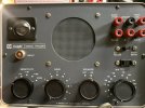
  • IMG_6039.jpeg
    IMG_6039.jpeg
    113.3 KB · Views: 22
  • IMG_6040.jpeg
    IMG_6040.jpeg
    108.8 KB · Views: 22
Last edited:
Register to hide this ad
Hello. First thing I'd check, is if the signal tracer is in good condition, working as it should. The fact that touching a component caused a short (if you didn't short something with the probe), makes me think that the unit or the probe could be internally shorted.

Then, you usually follow the signal along a schematic or following the PCB traces. Regarding the capacitor body, many times a signal is present at the cap body, you need a schematic to see that. Some large capacitors could have insulated cases, but in small electrolytics the case is usually connected to the negative lead .
 
Talk about over complicating things. :)

The manual is easy to find. https://bama.edebris.com/manuals/knight/83y135 I suggest thoroughly testing the signal tracer before using it. Instructions are in the manual. If it checks out per the manual, I would use a DMM to test that there is no voltage on the probe. I would also verify that there is high resistance between the probe and ground. Then I would test the signal tracer with a known good audio signal, preferably isolated with a 10uF cap to protect the source.

After doing all that, I would put the signal tracer on a shelf and admire it for the useless antique it is. I have built many Knight Kits as a kid. It was fun and I learned a lot. But all that equipment is useless today because there is so much better equipment available that is simpler, works better, is faster, and provides more information. The signal tracer I use is made of spare test leads, a capacitor, and half of an RCA cable plugged into the aux input on my bench receiver.

As for where to place the probe, use the schematic of the equipment under test. You are looking for an audio signal, so find conductors in the signal path. Connect the probe's ground lead to the ground of the equipment under test. Touch the probe to an exposed conductor in the signal path. I like to start at a point in the signal path where I know the signal is good, such as at the input connector where the signal generator/source is connected.

Using the Knight probe, expect to destroy stuff if the clunky probe slips. Mini-grabbers are my probe of choice if I need to make contact longer than momentarily. For momentary probe contact, I use an insulated probe that has only the very tip exposed. If I really wanted to use the Knight probe, I would clip a proper test lead to the probe tip and secure the Knight probe so it is stationary.
 
Talk about over complicating things. :)

The manual is easy to find. https://bama.edebris.com/manuals/knight/83y135 I suggest thoroughly testing the signal tracer before using it. Instructions are in the manual. If it checks out per the manual, I would use a DMM to test that there is no voltage on the probe. I would also verify that there is high resistance between the probe and ground. Then I would test the signal tracer with a known good audio signal, preferably isolated with a 10uF cap to protect the source.

After doing all that, I would put the signal tracer on a shelf and admire it for the useless antique it is. I have built many Knight Kits as a kid. It was fun and I learned a lot. But all that equipment is useless today because there is so much better equipment available that is simpler, works better, is faster, and provides more information. The signal tracer I use is made of spare test leads, a capacitor, and half of an RCA cable plugged into the aux input on my bench receiver.

As for where to place the probe, use the schematic of the equipment under test. You are looking for an audio signal, so find conductors in the signal path. Connect the probe's ground lead to the ground of the equipment under test. Touch the probe to an exposed conductor in the signal path. I like to start at a point in the signal path where I know the signal is good, such as at the input connector where the signal generator/source is connected.

Using the Knight probe, expect to destroy stuff if the clunky probe slips. Mini-grabbers are my probe of choice if I need to make contact longer than momentarily. For momentary probe contact, I use an insulated probe that has only the very tip exposed. If I really wanted to use the Knight probe, I would clip a proper test lead to the probe tip and secure the Knight probe so it is stationary.
Thanks for the info. I think you are exactly right. That kit looks great, but probe is clunky and is prone to short something. I found this and am planning to give it a try.
Thanks again.
 
Thanks for the info. I think you are exactly right. That kit looks great, but probe is clunky and is prone to short something. I found this and am planning to give it a try.
Thanks again.

What you found is an audible continuity tester that checks passive circuits that have high resistance. From the manual: "Tests continuity of circuits, components and cables." You could possibly modify that tester to provide a proper audio input and do signal tracing for testing audio equipment.

If you plan on testing audio equipment, you need proper equipment. For basic continuity tests, you can use an ohmmeter. Some ohmmeters even have a beeper function. No special equipment needed because everyone should have a multimeter.

If you plan on signal tracing live equipment, you need a signal generator and a signal tracer.

The signal generator can be almost any audio source plugged into an input if the equipment is a preamp. For amps, your audio source needs a volume control. I use the headphone jack on an old phone plugged into a line level input. A signal generator app allows me to set frequency and amplitude. If you plan on injecting the signal into the circuit, you should use a proper signal generator.

Then you need a way to detect the injected audio signal. Normally that is an isolated device that requires a ground and a positive connection with the positive connection being the probe.
 
Back
Top Bottom