• The move to the new server is done. There are some software and database maintenance updates in process. This has us passing the hat around to help out. We appreciate any donations. Seriously, even a dollar helps. The payment page may be found here - https://www.audiokarma.org/support.html

Transistor replacement soldering question

Is it possible to post a PDF file?
18869816_10154559960652551_2019044658_o_zpsnqwvfywo.jpg
 
The schematic specifically shows and lists R358, R360, R366, R368, R374, R374, R376, R382 & R384 as safety critical 4R7 Fusible 1/4W resistors - they would appear to be base stoppers on all (8) of the outputs of that channel. I assume they've all gone high from over-current.

R370 is listed as a 0R22 3W Metal Film - looks like one of the emitter resistors. Can't see how or why that would measure high.

Not sure how to post a decent sized schematic - but as Avionic noted, the hifiengine site is quick, free, and very useful.
 
There is an element of 'safety', and 'damage limitation' associated with the 4.7ohm ¼ watt resistors, personally I wouldn't increase the wattage of those resistors. After finding and replacing the damaged semiconductors, I would replace the resistors like for like. After all, they aren't burnt and open circuit in the good channel, yes? - and as safety components you WANT them to fail open circuit when there is a circuit malfunction.
 
Transistors mounted without heatsinks must dissipate heat through their leads, so shorter is better in that respect, but they're more likely to get damaged by soldering heat. Pick your poison.

The black band doesn't signify resistance value. It's meaning might not be standardized at all, but there's bound to be someone here who knows more on that topic.

In this situation, I use a surgical clamp as a heat-sink and clamp the leads between the component and board. This way I can solder the leads without putting excessive heat on the component. If the component uses the leads to dissipate heat, why would shorter be better? Longer leads would have more heat dissipating surface area
 
Just referring to the pcb raised component mounting: look up 'xuron' lead forming pliers to bend the leads in a scissor shape that give the component a sturdier mount. Can use on said ic's, diodes and resistors in pic #1 offers better cooling (and the Ic's have been replaced in that pic as factory would mount them bout a half inch max. If voltage regulators i.e. in a ps circuit that appear hot you can glue on scrap aluminum to act as a heat sink.

I suggest the pliers because it also offers a 'stop' against the pcb when mounting thru holes. Then bend solder and cut. or if good? insert and bend and cut then solder :D
 
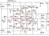
Link to schematic: https://www.hifiengine.com/manual_library/nad/218-thx.shtml
So far I found:
Q326(C3788), Q318(A1478) shorted
Q338(D1975), Q342(D1975), Q344(B1317) shorted
Q332((A1837) shorted
R358, R360, R366, R368, R374, R376, R382, R384 all 4R7F reading mega ohms out of circuit.
R370 3W 0,22 ohm cement resistor reading mega ohms out of circuit

All this in the right channel power amplifier board
According to previous owner, damage probably caused by shorted speaker output.
Sorry about the delay. I finally join the hifiengine and got the schematic.

What you have is a severe blow out of the amp where you burned a lot of power transistor. It is normal for those 4.7ohm resistor to blow to protect from fire. You should use back the 1/4W 4.7ohm, DON'T change to 1/2W. This is serve as fuse.

I am not familiar with the black bend fusible resistors, I'll let other's that have experience to tell you what to buy. The important thing is to put back the same type resistors.

Did you change Q340 even it is not blown? If you bought these transistors in one batch, I would change Q340. Q340 has to match with Q344. If you bought one extra, replace Q340.

BUT if you don't have an extra from the batch buy, don't worry about it. This is because chances when you order a few at one time, those transistor are from the same production lot and have better matching. If you order again, it might be from a different lot and won't match, then you might as well take a chance on the original transistor already in the circuit.
 
Last edited:
If the component uses the leads to dissipate heat, why would shorter be better? Longer leads would have more heat dissipating surface area
Because it's normally assumed that PCB tracks are the primary means of heat dissipation. This isn't true in all cases, of course, but you will see this assumption commonly used in device datasheets.
 
I don't think you should count on leads and pcb trace for heat dissipation. Also, this is not even the case for OP. His circuit has a melt down that burned the resistors.
 
Sorry about the delay. I finally join the hifiengine and got the schematic.

What you have is a severe blow out of the amp where you burned a lot of power transistor. It is normal for those 4.7ohm resistor to blow to protect from fire. You should use back the 1/4W 4.7ohm, DON'T change to 1/2W. This is serve as fuse.

I am not familiar with the black bend fusible resistors, I'll let other's that have experience to tell you what to buy. The important thing is to put back the same type resistors.

Did you change Q340 even it is not blown? If you bought these transistors in one batch, I would change Q340. Q340 has to match with Q344. If you bought one extra, replace Q340.

BUT if you don't have an extra from the batch buy, don't worry about it. This is because chances when you order a few at one time, those transistor are from the same production lot and have better matching. If you order again, it might be from a different lot and won't match, then you might as well take a chance on the original transistor already in the circuit.

Thank you for your answers

I have bought all 4 (driver?) transistors new Sanyo C3788 and A1478 that would be Q318, Q320, Q326, Q328

Also bought 5 sets of power transistors to replace the BJT D1975 + B1317 (discontinued) Replacements are Matsushita 2SD1718 and 2SB1163
Should I replace all 8? They seem to be arranged in a 4+4 configuration ?
The Q332 I guess is a voltage regulator ?

Resistors on their way 4,7 ohm 1/4 watts
As for the two "legged" emitter/cement resistor 3W 0,22 ohm I have not found yet...
.
I have decided to mount heatsinks on the pcb mounted transistors, I have 2 more of these amps that show the same traces of heat damage,
even though those other 2 amps are not hard driven.

On a sidenote
Also going to replace speaker protection relays.
These relays when old/worn, affects sound quality.

Again thanks for taking the time to answer.

Best regards
KO
 
A big thank you to all for taking the time to answer my questions. It is highly appreciated :bowdown:

Best regards
KO
 
Last edited:
Thank you for your answers

I have bought all 4 (driver?) transistors new Sanyo C3788 and A1478 that would be Q318, Q320, Q326, Q328

Also bought 5 sets of power transistors to replace the BJT D1975 + B1317 (discontinued) Replacements are Matsushita 2SD1718 and 2SB1163
Should I replace all 8? They seem to be arranged in a 4+4 configuration ?
The Q332 I guess is a voltage regulator ?

Resistors on their way 4,7 ohm 1/4 watts
As for the two "legged" emitter/cement resistor 3W 0,22 ohm I have not found yet...
.
I have decided to mount heatsinks on the pcb mounted transistors, I have 2 more of these amps that show the same traces of heat damage,
even though those other 2 amps are not hard driven.

On a sidenote
Also going to replace speaker protection relays.
These relays when old/worn, affects sound quality.

Again thanks for taking the time to answer.

Best regards
KO
I use these resistors ( not the same value ) for my amp:http://www.mouser.com/ProductDetail/KOA-Speer/MOSX3CT631RR22J/?qs=OpdMUBmMlYYxauT324hoog==

I would change Q340, that's the main one of concern. Your amp literally has two output sections, one driven by Q332 that mostly burned. The side driven by Q336 is ok, no need to change it. I don't like to change anything unless it is necessary.

The key thing to check check as follow:

Bias resistors.JPG

After you adjust the bias ( very important) according to the manual. check the voltage across the 4 pairs of resistors, each pair should match to within 3 to 5mV( max). It would be nice to have the both groups labeled A, and both group labelled B matched to within 5mV also. In your case half of the power transistors are not burned so hopefully it was matched in factory. Q344 is new, it's not likely to match with Q340. That's why I want you to change Q340.

But it's all about the numbers you read. You can even leave Q340 alone, fix everything, adjust the bias and do the measurement to decide. You post the reading of all the eight resistors and I will tell you exactly whether it need further work or not. Don't just change out anything unnecessary.
 
BTW, this looks to be a good amp. It is Current feedback frontend, 3EF( tripled emitter follower) output stage and 4 pairs of output transistor. Looks to be a much better than average amp.
 
[
Just referring to the pcb raised component mounting: look up 'xuron' lead forming pliers to bend the leads in a scissor shape that give the component a sturdier mount. Can use on said ic's, diodes and resistors in pic #1 offers better cooling (and the Ic's have been replaced in that pic as factory would mount them bout a half inch max. If voltage regulators i.e. in a ps circuit that appear hot you can glue on scrap aluminum to act as a heat sink.

I suggest the pliers because it also offers a 'stop' against the pcb when mounting thru holes. Then bend solder and cut. or if good? insert and bend and cut then solder :D

I had no idea that these pliers existed but I've just ordered a pair. Nice!
Back to your regularly scheduled repairs.
 
BTW, this looks to be a good amp. It is Current feedback frontend, 3EF( tripled emitter follower) output stage and 4 pairs of output transistor. Looks to be a much better than average amp.
I love them, I think they are much underrated,
 
Yes low distortion at minimal rated power 'gain' so that the speakers do not get over driven. Avoid clipping the amp and thus the speakers. even simple lab tests show same that speakers can be driven to extreme with minimal output.
 
Good evening

I got some new resistors from a German dealer today
They are 4,7 OHMS 1/4 Watt resistors 5% carbon film type
My concern is they are less than half the size of the ones I'm replacing, Is this a problem ?
19074719_10154580098412551_1703186531_o_zpsehav5pe2.jpg


Best regards
KO
 
Back
Top Bottom
