• The move to the new server is done. There are some software and database maintenance updates in process. This has us passing the hat around to help out. We appreciate any donations. Seriously, even a dollar helps. The payment page may be found here - https://www.audiokarma.org/support.html

Transistor Replacements for Darlington/BJTs & Outputs Kenwood KA3700

Chris Dykes

New Member
Hi All,

I've done as much legwork as I can to identify good replacement options for the driver and output transistors in the nice little Kenwood KA3700 amp.

I would love opinions on selecting the best replacement options. I see that NTE - while convenient - is often maligned as being low or inconsistent quality.

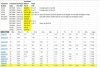
I've attached a schematic of the Amp board and my simple spreadsheet identifying the original transistors.

On the spreadsheet you can see that I've pulled a sample list of options for the first transistor showing measurements and possible replacement options. I can do so for each one to get the specs.

I’ve been doing a lot of speaker rebuilding including crossovers. I’ve built a Dynaco ST400 Solid State amp with new driver boards that I assembled – so I’m good with soldering and assembly.

What I need to learn is more about diagnostics, testing and design.

I hope to use this lovely, simple little amp as a great learning opportunity.

Thanks in advance!Amp Board Schematic.JPG Transistor and Diode Parts for AK Forum.JPG
 
Register to hide this ad
Ok, so the VO-3C diode is a 200V PRV 1.3A diode as per the VO series datasheet at http://www.hitachi-power-semiconductor-device.co.jp/en/products/diode/pdf/pde-v03-2.pdf The typical go-to series is the 1N400x, so 1N4003 is the one rated at 200V PRV. There is a newer "ultra fast soft recovery" kind of this same diode and UF4003 would be the 200V PRV version... but both those series are only good to 1A, so you'll have to go with a beefier diode. So, the next-up-in-current-handling series are the 1N540x and UF540x. If you want the standard, works-fine repllacement then look for the 1N5402 (200V and 3A). If you want a mild "upgrade" you'd go for the UF5402 (200V and 3A). (And by "upgrade" I mean it is very unlikely you'd hear any difference.)
 
Last edited:
The STV-3H is a no-longer-produced varistor to help bias track to the temperature of the output transistors (typically affixed to their heatsink). This is a common replacement need in vintage gear (people often break these when moving them) and we're in luck because the top experts at Audiokarma have contributed excellent research on how to replace these varistors with modern diodes in series http://audiokarma.org/forums/index.php?threads/replacing-the-stv-3h-and-4h-diodes.279530/ as well as great ideas on how to "make" the new diodes into a temperature-conducting unit that works the same as the original varistors like this http://audiokarma.org/forums/index.php?threads/kenwood-ka-5700.768090/#post-10525760 or this http://audiokarma.org/forums/index.php?threads/replacing-the-stv-3h-and-4h-diodes.279530/page-2#post-3446343 So, you'll need to order THREE diodes like UF1004 and maybe a few extra so you have spares during the make-a-new-STV-3H process.
 
The 2SC1318 is a device known to "go noisy" or fail over time as per http://www.audiokarma.org/forums/index.php?threads/top-ten-worst-transistors-noisy-failure-prone-whatever-and-replacements.731653/. The 2SC1318A is the same device, just a newer higher-voltage model. http://rtellason.com/transdata/2sc1317.pdf and http://www.secosgmbh.com/datasheet/products/SSMPTransistor/TO-92/2SC1318A.pdf. A starting point for replacements would be KSC2383Y or KSC2690AY. Both of those devices exceed the Vcbo, Vceo, Ic and Pd ratings... but the Vebo is only 5V versus the 2SC1318's Vebo of 7V. So, you'll need to look at the schematic and figure out "is this transistor getting more than 5V at its base in my application?" If not, if it is getting 5V or less, then either the KSC2383 or KSC2690A would be a good replacement. The replacements will be available in different gains (the hfe rating), so you'll want the one rated "Y". So, you'd search for KSC2383Y or KSC2690AY. Both these replacements have the same ECB pinout as the original device, so you'd install them the same orientation. The KSC2690 is a little larger device, a TO-126 package instead of the TO-92 package, but that's fine you just may need to enlarge the holes in the PCB a tiny bit to fit the larger legs of the KSC2690 through.
 
The 2SC1213A is an audio frequency amp as per https://www.renesas.com/zh-cn/doc/products/transistor/002/r07ds0432ej_2sc1213ak.pdf and it is NOT low noise, so with a Vcbo of at least 50V, a Vceo of at least 50V, a Vebo of at least 4V, capable of handling at least 500 mA current Ic, and dissipating at least 400 mW Pd, that gives you some very-common replacements like KSC2331 and KSC1008. The pinout for the 2SC1213A is ECB so the KSC2331 is the same (ECB) and the "-C" version of the KSC1008 (so, KSC1008C) is ECB. You'd want a hfe gain of somewhere in 100-320, so you'd order either KSC2331Y or KSC1008CY.
 
The 2SC1775 looks like a complement to 2SA872, so you'd want to replace those in complementary pairs (I'm guessing without looking at the schematic). These are nearly a perfect case for the modern, low-noise, complementary pair of KSC1845F and KSA992F.
 
The 2SD526 is a power output device http://rtellason.com/transdata/2sd526.pdf. You'd really want to know what gain range (hfe) your devices had or the schematic called for. The data sheet says there were R, O, and Y hfe classes, so you'd want to match that with your search in Mouser or similar site. A transistor (bipolar junction) in a TO-200 package with Vcbo of 80V or higher, Vceo of 80V or higher, Vebo of 5V or higher, able to handle Ic 4A of current or more, and able to dissipate Pd 30W or more. And has "audio amp" or "audio frequency power amp" in its application description. There is a modern model, the KSD526 or you could use a similar MJE15034, MJE15032, MJE15030, or MJE15028. If this is the output transistors, you'll want to replace all these with the same type at the same time.
 
The specs on the 2SC1827 http://pdf.datasheetcatalog.com/datasheet/WINGS/2SC1827.pdf are seemingly identical to the KSD526. Do you have a mix of these models in the same spot in your KA-3700? Like someone replaced the original with a different device? I guess it doesn't matter too much as the replacement recommendations for the 2SD526 above are the same for the 2SC1827
 
(Sorry about repeating the Facebook posts here, but I thought future searchers would find it easier here. And the smarter folks on AK can chime in.)
 
I am not a fan of the shotgunning-every-transistor approach.

No doubt, many will not agree as this seems to be a trend the past couple of years or so. To me it seems that this is perceived as an extension of the concept of recapping, i.e. if replacing every electrolytic is a good thing then by the same logic, replacing every transistor must be an even better thing. I do not agree with that "logic". Capacitors, and their roles in circuits, are simpler than transistors and their roles where subtleties exist which are, IMHO, not thoroughly enough considered in many cases, especially when the re-transistoring is being done by novice rebuilders.

just my .02 ¢ on that subject, not trying to start a debate or derail this thread.


@dlucy no offense to you. I feel like you have provided very good info in line with the OP's request

@Chris Dykes FWIW, my approach would be to replace: (1) any known trouble makers (this type of info has been fairly well documented on AK, and dlucy has pointed out that "low hanging fruit" for your amp), (2) relay driver transistor, and (3) if unable to get decent DC offset values, then match and install new input differential pairs. Other than that, I would leave transistors that are working alone.
 
Last edited:
I am not a fan of the shotgunning-every-transistor approach.

@dlucy no offense to you. I feel like you have provided very good info in line with the OP's request

No offense taken, @roger2 . When done respectfully, as you have done here, differences in opinion and approach here on AK just lead to more learning. In my opinion.
 
Is your KA-3700 the same as the KA-3750 in this thread? http://www.audiokarma.org/forums/index.php?threads/how-far-can-one-go-ka-3750.728422/ I know that some Kenwood models have bronze-faced European equivalents with a "50" added to their model number. My KA-9150 is just a multi-voltage bronzed-faced KA-9100.[/QUOTE
Is your KA-3700 the same as the KA-3750 in this thread? http://www.audiokarma.org/forums/index.php?threads/how-far-can-one-go-ka-3750.728422/ I know that some Kenwood models have bronze-faced European equivalents with a "50" added to their model number. My KA-9150 is just a multi-voltage bronzed-faced KA-9100.
Thanks Doug. I will check it out!
 
I am not a fan of the shotgunning-every-transistor approach.

No doubt, many will not agree as this seems to be a trend the past couple of years or so. To me it seems that this is perceived as an extension of the concept of recapping, i.e. if replacing every electrolytic is a good thing then by the same logic, replacing every transistor must be an even better thing. I do not agree with that "logic". Capacitors, and their roles in circuits, are simpler than transistors and their roles where subtleties exist which are, IMHO, not thoroughly enough considered in many cases, especially when the re-transistoring is being done by novice rebuilders.

just my .02 ¢ on that subject, not trying to start a debate or derail this thread.


@dlucy no offense to you. I feel like you have provided very good info in line with the OP's request

@Chris Dykes FWIW, my approach would be to replace: (1) any known trouble makers (this type of info has been fairly well documented on AK, and dlucy has pointed out that "low hanging fruit" for your amp), (2) relay driver transistor, and (3) if unable to get decent DC offset values, then match and install new input differential pairs. Other than that, I would leave transistors that are working alone.
Thanks Roger! I am going to start with the output transistors that I know are shorted. I thought I would use this amp as a learning experience and work through each board one component at a time. I really would like to learn to use an oscilloscope for testing and diagnostics
 
I thought I would use this amp as a learning experience and work through each board one component at a time. I really would like to learn to use an oscilloscope for testing and diagnostics

There is a really interesting use of a an oscilloscope for part-by-part testing, in-circuit, for stereo gear. The idea is "buy or make a curve tracer, hook it up to an oscilloscope, and test each leg of each component, channel by channel, looking for a leg (of some component) that yields a different pattern on the 'scope than the matching leg in the OTHER channel." It's a fascinating idea, I haven't done it yet, but I plan to. Sounds like this is purpose-made for your plan. https://pe2bz.philpem.me.uk/Power/- LV/Site-900-WallXformers/octopus.html
 
Thanks Roger! I am going to start with the output transistors that I know are shorted. I thought I would use this amp as a learning experience and work through each board one component at a time. I really would like to learn to use an oscilloscope for testing and diagnostics

Your original post did not mention blown outputs, so I mistakenly assumed this was re-transistoring for its own sake. But that being the case, personally I would:
---yes, stay away from NTE
---would do drivers as well (Qm9-Qm12)
---NOT change the varistors without good cause
---test thoroughly after replacing drivers and main outputs. No need to go too far and then have to back-track if there are problems.
see posts 5,10 http://www.diyaudio.com/forums/solid-state/269466-to92-transistor-replacement.html

Another thing that I would do in repairing an amp with blown outputs is replace the NFB loop electrolytic caps. Hard to see on your schematic (AK should allow larger jpgs!) but it appears these are Cm13, Cm14. I would use audio grade caps like Elna Silmic II or one of the top Nichicons like KZ or FG, and increase the voltage rating of those replacements to at least 16V.
 
Last edited:
Back
Top Bottom