• The move to the new server is done. There are some software and database maintenance updates in process. This has us passing the hat around to help out. We appreciate any donations. Seriously, even a dollar helps. The payment page may be found here - https://www.audiokarma.org/support.html

Transistor Testing

firecat

New Member
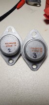
Is it normal for there to be a voltage drop from emitter to base collector? All four of my transistors have this and all other measurements check out. I believe they are PNP, honestly can't find a whole lot of info on them. I am recapping an old montgomery ward airline amp and I pulled them out just to check.

edit. I meant collector not base my bad.
 

Attachments
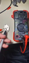
  • TO-3 emmiter to collector.jpg
    TO-3 emmiter to collector.jpg
    87.9 KB · Views: 31
  • pnp transistor.jpg
    pnp transistor.jpg
    93.6 KB · Views: 30
Last edited:
Register to hide this ad
Transistors act like diodes from leg to leg, so yes, you should have a voltage drop. Should read OL in the opposite direction. You will get two diode junction voltage drops from collector to emitter.
 
I meant to say from emitter to collector but said base on accident, but I do get what seems to be normal readings from emitter to base and collector to base. And get open circuit 0L from B to C, B to E, and C to E but not from E to C which is where my question comes in.
 
Without an actual transistor tester, when I use my analog meter, I usually just test them as diodes between the base and emitter.
 
You will get two diode junction voltage drops from collector to emitter.
Not true, because there is always one junction in reverse. In a good silicon transistor, you will read OL in both directions between the emitter and the collector.

In germanium transistors, the situation can be very different. Germanium transistors have much more leakage between base and collector than silicon transistors. When the positive probe is connected to the emitter and the negative probe on the collector, the leakage resistance between the base and collector will allow a small current conduction in the base, and the transistor will turn on (for a pnp). For a npn germanium transistor, the transistor will turn on when the positive probe is connected to the collector and the negative probe on the emitter. This is normal for a germanium transistor but if you have this with a silicon transistor, it is a defective silicon transistor or a "pre-biased" silicon transistor.
 
Well then follow up question. Can I assume I have a germanium transistor? Again, I can't really find a lot on mine (no data sheets or anything), only thing I can find is that an NTE104 can be used as a replacement. A really quick google search says that silicon transistors weren't used in the audio business until circa 1966 and I believe mine may be from before that, which I guess I'm not 100% sure of either.
 
Let’s see some pictures of the Airline!
I recently dug mine out and hooked it up.
I posted a schematic here some time ago.
 
Let’s see some pictures of the Airline!
I recently dug mine out and hooked it up.
I posted a schematic here some time ago.
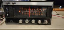
I just dug through your posts to see by the off chance that it's the same schematic for mine. Very close, sadly mine is GHJ 2549A which if somebody stumbles though here and has any info on mine that would be incredibly helpful. Didn't even bother asking because I had a hard time finding anything even close to my model number. I already recapped the amp side so you'll sadly not get to see it in it's original beauty, blown cap and all. But I'll see what I can do.
 
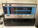
Here’s mine doing garage duty for grilling tunes. Sadly the FM has a tone coming through that it shouldn’t have. My phone hz app can’t pick it out but it’s a 8-10khz annoying tone. Fortunately the tape input is free of this. I’ve never adjusted the coils on anything yet but maybe this old Airline is the thing to learn on.
 

Attachments

  • IMG_6176.jpeg
    IMG_6176.jpeg
    122.1 KB · Views: 23
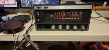
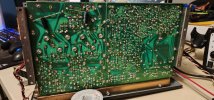
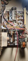
So I finished recapping, which I initially did because of a really loud AC hum. I instantly saw the capacitor that I suspected was the problem (cracked down the side and bulging and cracked on top). Anyways I believe what I did worked I get decent sound through all inputs that I could test on my desk AM, FM, and tape. However I only get sound through my right channel, and absolutely nothing through my left. How do I go about diagnosing what the problem might be? Could it be a transistor is blown? Like I said All transistors tested very similarly apart from one that had 100mV voltage drop from emitter to collector instead of the ~80mV I got with the other three. It isn't poor soldering on the speaker end (don't worry I don't trust my soldering skills either), I switched my RCA plugs around just to check if both speakers worked and still only the right channel did anything but obviously the sound came through the other speaker.
 

Attachments

  • Airline GHJ-2549a.jpg
    Airline GHJ-2549a.jpg
    76.6 KB · Views: 20
  • Airline testing with speakers.jpg
    Airline testing with speakers.jpg
    83.3 KB · Views: 22
  • back of board.jpg
    back of board.jpg
    139.1 KB · Views: 19
  • top of board.jpg
    top of board.jpg
    109.7 KB · Views: 19
I would love to. However, since this has went through 3 owners now it is now lost to time. I have looked around the internet trying to find one but to no avail. GHJ-2549a seems to be the product number for the entire console system that this came out of which includes, this receiver, a V-M 1296 turntable, the console itself, the speakers. Bradbrews did have one for his GHJ-2537, 2547, 2557 (I'm not sure which), and after glancing through his it does look to be similar to mine just laid out differently.
 
I think your initial question is resolved - it is most likely a germanium transistor which can have enough leakage to give the results you saw. Might try shorting the base to the emitter and then testing C to B/E in the direction that was giving you the questionable result. .
 
You can always take voltage or ohm checks between the channels. Also check the mono/stereo and the selector switches for possibly being dirty.

If you switch to mono and both speakers work, then we know the left and right amps are working and it could just be a dirty switch.
 
Check the speaker switches and the scratch filter switch. Mine are all poor performers. I’m very close to bypassing them all.
 
Switches seem to be working fine. I get continuity across them when the switch is on and none when they are closed. I did clean them with a bit of contact cleaner before I started this project. I unfortunately don't have a scope to test where I am losing my signal, too bad I'm currently not at school or I could just bring it in and trace my signal and watch where it disappears. Cade are you talking take measurements when it's trying to output sound or when the amp is switched off?
 
Voltage measurements when it is powered up.

Ohm measurements when it is powered off and unplugged.
 
Balance knob is set correctly. I have set this project to the side for now and will finish it when I go back to college. There I will be able to use an oscilliscope so I can trace exactly where I lose my signal. Thanks to everyone who stopped by and had some input for me, really appreciate it!
 
Back
Top Bottom