• The move to the new server is done. There are some software and database maintenance updates in process. This has us passing the hat around to help out. We appreciate any donations. Seriously, even a dollar helps. The payment page may be found here - https://www.audiokarma.org/support.html

Transistors - How can i identify EBC based on schematic?

PTL-Pioneer

Super Member
Hi all

Been reading up on things, specifically relating to an SX750. Lots and lots to read and try digest.
I understand using data sheets to identify the designation of each pin, when you have a new transistor to install..
How does one identify what the correct orientation is when replacing a transistor with no datasheet on the old transistor?

Is the clue in the symbol??
The base is obviously the the single vertical or horizontal line. But how do you identify which side is emitter and collector? Does this also depend on the type of transistor?

I have been looking at the SM for the SX750, pg 48 gives a nice 3D drawing of all the transistors and their pin id.
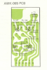
Looking at AWR-065 though it states there are 2SA1313 and 2SA726 which are not on pg48.
How can i easily identify the pins?

Thanks


00f4cefe-17e0-4f24-b268-719fcaeaaa93
 

Attachments

  • upload_2017-1-12_15-21-52.png
    upload_2017-1-12_15-21-52.png
    326.4 KB · Views: 45
Register to hide this ad
The emitter is the line with the arrowhead on it if that's what you want to know. If the old transistor is still in the circuit and you don't have a pin-out you can mark it before removing it if you think you're gonna need to know its pin-out later on for some reason. If the new transistor comes with a pin-out you put it in according to the schematic. Am I missing something?
 
Unfortunately, as some have found out, the service manuals and the silk screen indicators on the printed circuit board may be in error.

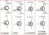
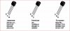
Below are some basic examples of transistor lead identification.

Capture2.JPG

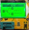
One of the basic component testers like this (less than 15 dollars)

Capture4.JPG

can be very useful in helping to determine component lead identification along with testing and identifying a wide range of parts.

Transistor lead identification may be performed using diode test function of a DMM. A basic transistor is like 2 back to back diodes and each internal diode may be checked just like a single diode in most cases.

Capture3.JPG
 
Unfortunately, as some have found out, the service manuals and the silk screen indicators on the printed circuit board may be in error.

Below are some basic examples of transistor lead identification.

View attachment 850449

One of the basic component testers like this (less than 15 dollars)

View attachment 850452

can be very useful in helping to determine component lead identification along with testing and identifying a wide range of parts.

Transistor lead identification may be performed using diode test function of a DMM. A basic transistor is like 2 back to back diodes and each internal diode may be checked just like a single diode in most cases.

View attachment 850450
Um... the pin-out comes with the new part - no need to buy any new gee-whiz toys to figure that out. If the schematic / board graphics are in error then he's gonna have to do some circuit interpretation.
 
Um... the pin-out comes with the new part - no need to buy any new gee-whiz toys to figure that out. If the schematic / board graphics are in error then he's gonna have to do some circuit interpretation.

I am not familiar with how to read a schematic to be honest. Maybe getting the tester is the easiest option for the unitiated like myself.
Amp i have works relatively well, so last thing i want to do is put a transistor in the wrong orientation and mess things up.

And i do hear that the manuals and boards can be marked wrong etc so i was just looking to literally foolproof the process by being able to identify the pins of the transistor that will be removed.
 
This is not so much about the new part as the old part per the OP.

Speaking in general, the replacement part may have a different pin out and it may be difficult to find accurate information on the old part.

Some replace functioning (although possible noisy and or less quality) transistors and may not be able to find accurate information on the original transistor, so they may have to rely on the PCB silk screen and or the service manual. The device I referenced can be of help in this situation, not to mention its basic function of testing parts for failure.

Just as an example of what a person might run into, they look up the old transistor on line and see one pin out, but this pin out does not match the service manual and or the PCB silk screen and the pin out of the new transistor may not match the old transistor. So which one is correct in terms of correctly installing the new transistor?

I found this information on line and it may or may not be correct.

Capture10.JPG

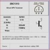
To the OP, did you mean 2SC1313? That is what is indicated in your picture. If so...

Capture14.JPG

And the following is following is accurate most of the time.

Capture15.JPG


Again, I make no claims about the accuracy of this information, but I hope that it helps.
 
I am not familiar with how to read a schematic to be honest. Maybe getting the tester is the easiest option for the unitiated like myself.
Amp i have works relatively well, so last thing i want to do is put a transistor in the wrong orientation and mess things up.

And i do hear that the manuals and boards can be marked wrong etc so i was just looking to literally foolproof the process by being able to identify the pins of the transistor that will be removed.

We posted with in seconds of each other.

We all started at the same place with regard to this knowledge (not knowing anything).

So do what you are comfortable with and what works for you. You will, like a lot of members here, learn as you go along.

And BTW, there are quite a few AK members that use the so called "gee-whiz toys" for diagnosis and some even test every part prior to installation. Not only are there problems with errors in the service manuals, data sheets and the units themselves, but you can run across defective and mismarked new parts.

The use of a component tester is very inexpensive risk management, especially for those just starting out and there is nothing wrong with just starting out, we all did it and it can be fun along the way.
 
I am not familiar with how to read a schematic to be honest. Maybe getting the tester is the easiest option for the unitiated like myself.
Amp i have works relatively well, so last thing i want to do is put a transistor in the wrong orientation and mess things up.

And i do hear that the manuals and boards can be marked wrong etc so i was just looking to literally foolproof the process by being able to identify the pins of the transistor that will be removed.
OK - I get it. Testing a semiconductor that you're removing in order to discover its pin-out and "verify" the schematic / board graphics prior to inserting the replacement part is a procedure completely alien to me. The part may not cooperate with you - it may be defective. OK - we're cool - just trying to figure out what the plan was.
 
Thank you very much for your help, apologies if i did not articulate my question adequately.
The reading and troubleshooting i have read about on AK when people are doing a recap, is that they end up putting a transistor in the wrong way and end up messing things up badly and having to do some detective work to go and fix the issue. If i ensure i know the pin ID of the transistors i am removing, and the datasheet for the new transistors hopefully i can avoid any issues relating to this.


The use of a component tester is very inexpensive risk management, especially for those just starting out and there is nothing wrong with just starting out, we all did it and it can be fun along the way.

Well put! Inexpensive risk management

Thanks you so much for all your help, genuinely very much appreciated
 
Unfortunately it seems that I'm gonna have to be blunt about this. IMHO the advice you've been getting from I LIKE MUSIC seems to be informed by folklore and a poor understanding of folklore at that. The chances of schematic / board graphics error are minuscule compared to the chances of getting ambiguous results in an electronic "pin-out" test of a defective semiconductor.

I understand that you're a newbie coming at this from a hobbyist background. And it's understandably difficult to separate the wheat from the chaff when it comes to advice. The modus operandi of I LIKE MUSIC follows a pattern of long, windy, lofty, contrarian, "concern" about things remotely likely to be issues - and the effect of this sort of performance can understandably be impressive. At any rate - had to say it - others invited to chime in.
 
Paultlaw

As an example Marantz is somewhat known, among others for their service manual errors. Errors are not limited to just transistors. There are a lot of test point errors, silk screen errors with regard to capacitor and diode polarity, parts mislabeled, alignment and adjustment procedural errors and even the occasional wrong transistor listed and incorrect pin outs. And even if there are not any errors, there are updates and revisions that may or may not be included in the service manual that you are using. You may be looking at a service manual that is not in error but may be for a different circuit board revision.

It is a good idea to take a lot of pictures and make a lot of notes, especially since you are just starting out.

I have not done a lot of refurbishing but have encountered 2SC458 two or three times. In my case they were in Akai tape recorders but I understand they were widely used by the industry in general.

Something I noticed though was that transistors designated 2SC458 could be either a square package with a sloped top or cylindrical with a flat front. It confounded me at first because oddly, their pin outs were mirror images of each other.


They indeed come in (at least) two versions;

nYfWWoa.jpg


sTngyWJ.jpg


Your meter is your friend. Takes about 15 seconds to determine which lead is the base. I always check as a sanity check when replacing transistors.
Background - when the Korean KSA733 and KSC945 with center base leads first appeared in the late 70's (Scott, Goldstar, Samsung and others) they looked just like 2SC945 and2SA733 (Center lead collector) and caused lots of headaches until people figured out what was happening.

BTW Loopstick "electronic "pin-out" test of a defective semiconductor." This is a straw man. The OP was asking about replacing functioning transistors as is often done when refreshing a piece of gear and wanting to to make sure the the replacement transistor is installed correctly and I never mentioned trying to determine the pin out of a defective transistor.

Even if there are no errors at all in any service manuals or PCB silk screens there is still the human error factor and the OP who is admittedly just starting out and not up speed reading schematics (and that is okay, we all had to start at one time) is just looking for information to use to reduce the risk of errors.

And if he were to jump into vintage Marantz gear, among others, he could be exposed to a fair number of errors.
 
BTW Loopstick "electronic "pin-out" test of a defective semiconductor." This is a straw man. The OP was asking about replacing functioning transistors as is often done when refreshing a piece of gear and wanting to to make sure the the replacement transistor is installed correctly and I never mentioned trying to determine the pin out of a defective transistor.
Oh. OK.
 
Very good thread on identifying piinout's on BJT's and some mosfets by ECHOWARS with comments from Mark The Fixer. Post #11 is of particular relevance.
http://audiokarma.org/forums/index.php?threads/bipolar-junction-transistor-testing-basics.43186/
This is interesting from the first post -
EchoWars said:
First you need a decent digital meter with a diode test function. Forget about using the ohmmeter part of your meter, it is way too unreliable for this.
I know he (EchoWars) advocates digital multimeters for newbie hobbyist type guys. I'm guessing that this warning about using the ohmmeter applies specifically to digital multimeters. It is (was) pretty routine to test diodes and other PN junctions with the ohmmeter function on analog multimeters.
 
Update: buying the tester was the best decision!! Really minimised the risk, cost very little, and if used could save you a lot of hair pulling.
If anyone ever reads this and is not sure, buy yourself some cheap risk management, you won't be sorry!!
Thank you all, especially user ilikemusic!!
 
Update: buying the tester was the best decision!! Really minimised the risk, cost very little, and if used could save you a lot of hair pulling.
If anyone ever reads this and is not sure, buy yourself some cheap risk management, you won't be sorry!!
Thank you all, especially user ilikemusic!!
Yeah - I LIKE MUSIC did a fantastic job reading your mind and understanding that you were planning on replacing fully functional parts. Something you never disclosed in any of your posting. For repair work using this form of "risk management" would be lunacy. But you're not repairing - you're "refreshing". You're doing like a recap - only with transistors. A "retrans". Anyhoo - glad it's working out for you.
 
Loopstick, thank you for acknowledging my somewhat prestigious psychic powers.:D:D:D

But in this case they were not needed. I simply read his posts.

Amp i have works relatively well, so last thing i want to do is put a transistor in the wrong orientation and mess things up.

For those of use that have been around since before the transistor was invented, paying close attention to the various transistor lead identification variations may be second nature.

In the case of the common TO-92 case style transistors, data sheets may show the flat side facing left, right, up, down and some may identify the leads from the rear.

Capture2A.JPG

And one showing flat side down.

Capture2C.JPG


All of this may be confusing for someone just starting out and remember we all were just starting out at some point in time.

So if an inexpensive device can help reduce the chance of making an error, and or reduce the worry that one might have for doing the correct thing, that is not a bad thing and for someone just starting out it is far from lunacy, be it a refresh of the transistors or a repair.

Of course the refresh and or repair can be done without a device like this, but that is not the point. If it reduces stress and or increases our enjoyment of the hobby, along with helping to prevent errors, that is not a bad thing.
 
Just finished the power supply on my Pioneer SX-1010 and would have put four of the transistors in backwards had I not checked them first with my DMM on diode check so good advise here. The service manual and data sheet showed the pin out was the same or I'm not reading them right. Anyhow glad I double checked and believed my meter.
 
Back
Top Bottom