• The move to the new server is done. There are some software and database maintenance updates in process. This has us passing the hat around to help out. We appreciate any donations. Seriously, even a dollar helps. The payment page may be found here - https://www.audiokarma.org/support.html

Triangle TE60-No sound on one Channel

Radas

New Member
Hello,
I own a Triangle TE60.
I don't have sound on one of the channels (Left).
The preamplification stage is fine.
I have 8V DC coming out of the Left speaker output. Ouch.
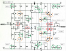
I’ve taken the following measurements:
TE60_1.png
I noticed a difference of about 10V DC on the MOSFETs.
Both should be at 48/49 V DC.

Thank you very much for your help.
 
Register to hide this ad
I noticed a difference of about 10V DC on the MOSFETs.

I hesitate to reply because I'm not very good at remote diagnosis, but I'll remark on a couple of points:
  • The schematic depicts only BJTs, no MOSFETs.
  • In the first stages of the amp, the transistors have resistors in their emitter connections, so if accessibility allows, you could examine the currents in those transistors by measuring the voltages across the emitter resistors. If you can also measure the BE voltages on those transistors, you could look for situations where the BE junction is forward-biased but there is no current; or where the BE junction is not forward-biased but there is current. Either situation would be likely to indicate a failed transistor.
 
A couple of other things seem odd:
  • If I understand your output transistor measurements, the DC offset at the output is negative. But you note 0.24VDC at C58 (once again, assuming I understand your annotations). If the output offset is negative but C58 is positive, the only explanation I can think of is that there is a source of unexpected leakage current into C58. T53 might be a suspect.
  • I can't make any sense of the annotation of 48VDC that seems to be associated with C88 (or maybe C68? I can't distinguish). What is that 48VDC measurement?
 
Hello,
Thanks a lot of for your replies.

T61 and T65 are: MJ15003 & MJ15004.
T62, T63 and T64 are: TIP41C & TIP42C
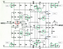
TE60_2.png
I have compared voltage between Left and Right Channel.
Normally 54VDC and 44 VDC should be 48VDC for Both.
Instead, I have 6VDC that are between GND and +Left speaker out.


For the 0.24VDC at C58: I've measured directly on both side of C58, it should be 0VDC?
The 48VDC is measurement of the voltage on + and - of each capacitor.
I will examine the current/voltage in resistor R82 R83 R84 R85 soon.
I've 0.45VDC between Base and emitter on T61 & t65
TE60_3.png


I've de-soldered:
1:T61 & T65 : still 6VDC on between GND and + speaker out.
2:T62 & T64 : still 6VDC on between GND and + speaker out.
3:T59 & T60 : still 6VDC on between GND and + speaker out.
4:T53 & T54 : still 1.4VDC on between GND and + speaker out.
But know i noticed that I have 10VDC on the channel that was ok at start.
I have checked every Transistor with a "Mtester", everything seems okay.

Thanks a lot for your help.
 
I think I am failing to understand your observations, so you should use caution with regard to anything I suggest. Nevertheless:

In the present state where there is a large offset at the output of the amplifier, the voltage at C58 should be close to the same as the output offset. Note that one terminal of C58 should be connected to the circuit ground, so if you measure any voltage on that terminal, something has gone wrong with the ground connections.

In general, if you de-solder any of the transistors, voltage measurements will not be meaningful. (To me, at least.) It is probably a good idea to not power up the amp if you have de-soldered anything. An exception is that the output transistors T61 and T65 can be entirely disconnected, and voltages should not change. (The only effect is that the amplifier will no longer be able to drive a normal load.)
 
Back
Top Bottom