Hi all
I'm fishing for a bit of help trying to fix an issue with this tuner. Hopefully someone out there has the time/inclination. It's a nice sounding tuner and I'd like to get it working, if I can.
The issue is a bit unusual. It will tune into stereo (with some effort) and sounds good. Once tuned, it will stay tuned for days. But in order to get it to tune in, I need to turn the dial quickly and then stop at exactly the point where it will tune to stereo. Generally a number of goes, sometimes many are required. Approaching the station frequency more gradually, as you would normally do rarely works. It's been like this since I got it several years ago but it's gradually getting harder to get it to lock onto stereo.
The service manual is at the following address:
 www.hifiengine.com
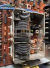
The issue suggested that it might be the contacts on the tuning cap, so I cleaned those and the control switches. This made no difference.
www.hifiengine.com
The issue suggested that it might be the contacts on the tuning cap, so I cleaned those and the control switches. This made no difference.
SoCal Sam has suggested cleaning the FM Oscillator (I understand this to be a variable cap very close to the tuning cap) but I'm not sure the symptoms match this fix. Anyway, I'd prefer to put off messing with settings until I've exhausted other options.
I've read that drift in the power supply can cause issues, so I checked this. There are discrepancies but I'd appreciate some input on whether this is the problem and trouble shooting.
The power supply (called VOLTAGE REGULATOR) is in the schematic at G3-4. It has three marked voltages (top down): 0.6V; -18V; and 14V.
I measure these at: 1.2V; -23.35; and 13.26V, respectively. The first two deserve most attention.
The AC output of the transformer is shown in the schematic as 18VAC on either side of the centre tap. I measured these as 16.7 and 16.5VAC.
16.7VAC goes through D26 and is filtered by C93, so with a low current draw (multiply by 1.4) gives close to the measured voltage of -23.35 (-18V on the schematic). A possible explanation is that there is reduced current draw from this voltage source, so it sits at the rectified-filtered voltage.
The measured voltage of 1.2V (0.6V on the schematic) is way out. Interestingly this voltage source converges with the negative voltage source (-18/23.35V) on Q13 (C5 on the schematic), which is the only drain on the negative source, save for a couple of 10M resistors in that vicinity of the schematic. Q13 is a PNP and the 0.6/1.2V source feeds the base, so elevated voltage would tend to reduce E/C current and the draw on the negative voltage source (-18/23.35V). But R115, 820K (also at C5) is in series with the Q13 collector, so query how much difference this might make to voltage at the power supply?
Suggestions much appreciated.
Cheers
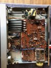
PS - I've included a picture but I'm not sure it adds much.
I'm fishing for a bit of help trying to fix an issue with this tuner. Hopefully someone out there has the time/inclination. It's a nice sounding tuner and I'd like to get it working, if I can.
The issue is a bit unusual. It will tune into stereo (with some effort) and sounds good. Once tuned, it will stay tuned for days. But in order to get it to tune in, I need to turn the dial quickly and then stop at exactly the point where it will tune to stereo. Generally a number of goes, sometimes many are required. Approaching the station frequency more gradually, as you would normally do rarely works. It's been like this since I got it several years ago but it's gradually getting harder to get it to lock onto stereo.
The service manual is at the following address:
Kenwood KT-900 AM/FM Stereo Tuner Manual | HiFi Engine
www.hifiengine.com
SoCal Sam has suggested cleaning the FM Oscillator (I understand this to be a variable cap very close to the tuning cap) but I'm not sure the symptoms match this fix. Anyway, I'd prefer to put off messing with settings until I've exhausted other options.
I've read that drift in the power supply can cause issues, so I checked this. There are discrepancies but I'd appreciate some input on whether this is the problem and trouble shooting.
The power supply (called VOLTAGE REGULATOR) is in the schematic at G3-4. It has three marked voltages (top down): 0.6V; -18V; and 14V.
I measure these at: 1.2V; -23.35; and 13.26V, respectively. The first two deserve most attention.
The AC output of the transformer is shown in the schematic as 18VAC on either side of the centre tap. I measured these as 16.7 and 16.5VAC.
16.7VAC goes through D26 and is filtered by C93, so with a low current draw (multiply by 1.4) gives close to the measured voltage of -23.35 (-18V on the schematic). A possible explanation is that there is reduced current draw from this voltage source, so it sits at the rectified-filtered voltage.
The measured voltage of 1.2V (0.6V on the schematic) is way out. Interestingly this voltage source converges with the negative voltage source (-18/23.35V) on Q13 (C5 on the schematic), which is the only drain on the negative source, save for a couple of 10M resistors in that vicinity of the schematic. Q13 is a PNP and the 0.6/1.2V source feeds the base, so elevated voltage would tend to reduce E/C current and the draw on the negative voltage source (-18/23.35V). But R115, 820K (also at C5) is in series with the Q13 collector, so query how much difference this might make to voltage at the power supply?
Suggestions much appreciated.
Cheers
PS - I've included a picture but I'm not sure it adds much.
Attachments
Last edited: