• The move to the new server is done. There are some software and database maintenance updates in process. This has us passing the hat around to help out. We appreciate any donations. Seriously, even a dollar helps. The payment page may be found here - https://www.audiokarma.org/support.html

Triode gain stage with local negative feedback - examples?

thorpej

AK Subscriber
Subscriber
Howdy folks...

One of the projects in my queue is to build a simple 3-or-4-input pre-amp for each of my kiddos ... for practical reasons, my son needs something to easily switch between at least two inputs on his amp (he recently inherited my wife's dual cassette deck and is having a field day with a bunch of my old tapes -- long live the 80s -- but still plugs in his iPod as well)... and the input of their amps aren't sensitive enough to drive to full power with a standard line-level source (this may be a good thing, but one should still strive for good performance from their equipment, right?). So, rather than a simple passive selector, I thought I'd add a gain stage and cathode follower.

Practically speaking, a total gain of around 2 from the pre-amp would be just about perfect. In order to keep distortion from the gain stage to a minimum, my thought was to use a 12AY7 for the gain stage (sufficient open loop gain and unlike the 12AX7, sufficient current at -2V to be able to use LED biasing) and apply a fair bit of local feedback to get the closed loop gain to around 2.5. Add a 12AU7 cathode follower (gain of about 0.95), and we're pretty close to an overall gain of 2.

I read over Merlin's on-line tutorial for triode gain stage with local feedback, but his site is very much focused on guitar amp building, so he glosses over a bunch of stuff related to this topic. I have his Hi-Fi pre-amp book, and plan to rummage though there for some more information, but I was also hoping that someone here in-the-know could point me at a reference to existing pre-amp designs that use local feedback.

There are a couple of issues in particular that are puzzling me a bit:
  • Merlin's tutorial leaves off things like grid leak / ground reference from the triode that gets the local feedback. My assumption was that the grid ground reference actually comes from the grid leak of any subsequent stage, but I'd like confirmation of this with some additional context. (http://www.valvewizard.co.uk/localfeedback.html)
  • The best place to put a volume control is on my mind... I was thinking between the gain stage and the cathode follower (pot serves as the grid leak for the cathode follower, the wiper connected to the grid), but I'd like to hear other suggestions as well.
Anyway, those are the two things on my mind, and I know there are a lot of smart people here who will probably be able to point out like 10 other things I should be concerned about, so have at it :)

And, as always, thanks!
 
Register to hide this ad
Of course if you put the pot between the two stages you would typically need to AC couple on both sides so that the pot runs with no static DC voltage on it.

Consider a voltage gain stage sandwiched between two cathode followers, but driving the voltage gain tube from its cathode rather than from its grid. This is the idea I've been mulling around for several years as I consider the best topology for a low gain preamp with off-the-shelf tubes like a 6SN7. Another way of thinking about it is to say that the first stage is a cathode coupled differential pair, but taking only the non-inverting output and feeding that to an output buffer. I think you would have the option in that case of adding local feedback to the grid of the voltage gain stage (i.e., the grid of the second triode in the differential pair).

I haven't thought much more about it than that, but it seem like it would work quite well. The key is driving the voltage gain tube from its cathode--that provides three advantages: lower gain, a non inverting output, and a place to hook local feedback.
 
That's an interesting idea ... That's the same sort of feedback topology that e.g. Marshall guitar amps use ... feeding back to the 2nd grid of the LTP phase inverter (the cathode-driven triode's grid is capacitively coupled to the feedback junction rather than to ground). But in that scenario, the feedback is taken from a fairly low impedance output (a tap on the output transformer... I guess one could take the feedback from the following buffer stage... but even that output impedance is going to be measured in the hundreds-of-ohms ... I guess I'm just concerned with how the feedback divider could potentially load down the gain stage.
 
Good questions. I haven't thought through it that far to know how to answer them, but yes, I sorta developed that rough idea after looking at some guitar amp phase inverter stages. However, I bet this is nothing new..someone probably tried it clear back in 1950 or something.
 
and a place to hook local feedback.

FWIW, in theory it's possible to hook back into the grid of an inverting gain stage, and this is how Merlin describes it, but I can't recall seeing a complete circuit with the previous and subsequent stages in context.

The Eico HF-85 also uses a couple of feedback loops in the final stages after the volume control (I'll call them A, B, and C):
  • 2 garden-variety gain stages (A and B), with signal taken from the output of the B (after the coupling cap) and fed back to the cathode of the A. The B's output is also sent to the "TAPE OUT" jack, so this may be, in part, a way to reduce the output impedance for that output.
  • After B is the tone control PEC, followed by gain stage C. Signal is again taken from the output of C (after the coupling cap) and fed back into a terminal on the PEC, thus forming part of the tone control.
There are no buffer stages on the HF-85.
 
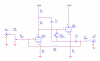
Here's a circuit concept that I sketched up for a related application. Closed-loop gain is set by R3 and R5. For a gain of two, I would make them perhaps 470K and 1M respectively. You could certainly add more loop gain and drive distortion into the dirt by using a high-mu tube for the input stage, with or without the bootstrap (C1). With it, open-loop gain comes close to the raw mu number for the tube. The neon lamp is over-voltage protection for the CF tube.

6SN7pre.png
 
Last edited:
Thanks, @BinaryMike, that's helpful... I was not DC-coupling to the cathode follower and attempting to take it after the gain stage coupling cap, but was getting confused about what to do about the following stage. I like the idea of taking it after the cathode follower because it deals with any non-linearities in that stage, as well. Taking it after the cathode follower also has the advantage of not loading down the gain stage with the feedback resistor.

(Yes, I was using a higher-mu tube -- 12AY7 -- open loop gain of 30-ish, and then using 390K for the grid resistor and 1M for the feedback resistor.)
 
Ok, now let's talk about Miller effect. The 390K grid resistor (in my schematic, not far away from the 470K suggested by @BinaryMike) is pretty large... On paper, my 12AY7 gain stage has an open loop gain of 30, which when multiplied by the 1.3pF g-a capacitance and added to the 1.3pF g-k capacitance of the 12AY7 gives 64pF. Unless I seriously flubbed the math, that's a low-pass roll-off of only 6.3KHz! This is a bit more gain than Mike's example circuit (bootstrapped, so the same as the mu of the 6SN7 -- 20), but the 6SN7 also has much higher g-a capacitance (3.8pF), so the open loop Miller effect would be roughly the same as my 12AY7. Merlin makes no mention of watching out for Miller in his local feedback tutorial.

I guess this gets back to @kward's other thread about Miller in the presence of feedback. I can't imagine that the high frequency response of this circuit is really that poor.

What am I missing here?
 

Attachments

  • Screen Shot 2017-01-25 at 12.50.18 PM.png
    Screen Shot 2017-01-25 at 12.50.18 PM.png
    218.6 KB · Views: 52
In this circuit arrangement, the input grid is a 'virtual ground' node, where input and feedback currents are subtracted (or summed with FB inverted). Any difference between those currents produces a signal voltage on the grid that is amplified to drive out the difference, so you end up with flat frequency response at the output node. The only bad consequence of HF rolloff inside the loop is that distortion can rise at high frequencies. Considering that your closed-loop gain target is so low, I say it's good to go. Distortion should be very low overall.
 
Alright, well here's my first draft, then. I didn't bother elevating the heater voltage because the 156V on the 12AU7's cathode is within the 200V max rating... but I've got it in the back of my mind. (I have plenty of juice available on the heater windings of the PT, so doing DC heaters is within the realm of possibility, too, if hum leakage is a problem.)

I'm also including the load line I drew for the 12AY7 -- as you can see, I chose an operating point that that says well within the linear region of operation for up to 1.4Vrms if input signal.
 

Attachments

You could certainly add more loop gain and drive distortion into the dirt by using a high-mu tube for the input stage, with or without the bootstrap (C1)
Tell me more about the bootstrap capacitor. What is its purpose?

@thorpej did you think about using another 12AY7 for the output buffer and run it at the same current as the input 12AY7 to get some distortion cancelation? Maybe not a big deal if you are using feedback though.
 
Tell me more about the bootstrap capacitor. What is its purpose?
The bootstrap forces the tap in the anode load resistance to track the output voltage, which makes the apparent anode load infinite if CF gain is unity. It's slightly less than that, of course, but you still end up with voltage gain nearly equal to the raw mu figure for the tube, and it's simpler than adding a CCS.
 
Tell me more about the bootstrap capacitor. What is its purpose?

@thorpej did you think about using another 12AY7 for the output buffer and run it at the same current as the input 12AY7 to get some distortion cancelation? Maybe not a big deal if you are using feedback though.

I didn't really think of using a 12AY7 for the buffer, actually, mostly because my brain immediately jumps to 12AU7 or 6SN7 for that application. I certainly could, I suppose... and it would make for a tidier build.
 
(As for the bootstrap, in addition to what @BinaryMike said, I think Merlin describes how the mechanism works in detail in one of his books... I'll see if I can dig it up later.)
 
And by making the anode load look infinite, it increases stage gain. (just like a CCS would). Ingenious.
 
And by making the anode load look infinite, it increases stage gain. (just like a CCS would). Ingenious.

Yup! Found the reference section 6.16 of Merlin's "Designing Valve Preamps for Guitar and Bass, Second Edition". So, visualize the inverted / amplified signal as it might appear at various points along the load resistor... 0 at the power supply side, and 100% at the plate side... let's pretend that 1/2 way through the resistor it's at 50%.

If instead you split the load resistor in half and superimposed the buffered signal from a unity gain cathode follower at the 1/2 way point, then because the AC signals are equal phase and magnitude on either end of the bottom load resistor, then zero AC current flows and the bottom load resistor appears to have infinite resistance. You can visualize that the load line is thus horizontal, i.e. the gain is mu.

Because real cathode followers don't quite have unity gain, there is still some small amount of AC current and thus in real life it's not infinite resistance, which is why you only get "nearly the mu of the valve". But achieving a gain of 90 is still pretty great.

A friend of mine does this in guitar amps all the time because he's using the cathode follower anyway to drive a tone stack.
 
Back
Top Bottom