• The move to the new server is done. There are some software and database maintenance updates in process. This has us passing the hat around to help out. We appreciate any donations. Seriously, even a dollar helps. The payment page may be found here - https://www.audiokarma.org/support.html

Troubleshooting help needed.

joshvito

Active Member
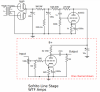
I built a single ended tube preamp (the circuit is here https://wtfamps.com/sofrito-preamplifier/). The preamp seems to be working great, however, my amplifier kicked into protection mode this evening. So, I decided to check to see if there was DC on the outputs of the preamp. I hooked up my Multi meter up to the output of the preamp and it the DC voltage jumps all over from -100mV to ~120mV with no input signal and not hooked up to the amp.

What could cause my amp (Marantz PM8005, input sensitivity is 1.6v 15kohm) to go into protection mode? Is the addition of my newly built preamp just coincidental? The system was working fine for 6 or 7 two hour listening sessions. The last session, I got about 20 minutes through a record before the amp went into protection mode.

Removed the preamp from the system, and using the built in preamp of the Marantz, and currently about 30 mins into a record and it's playing okay.

There is a little noise, but it could be the record as it is new and the first spin.

Any troubleshooting tips are appreciated.
 
Register to hide this ad
Maybe posting a schematic might help. Maybe an earthing issue. Can you measure the ac and dc voltage between the grounds on the PA input jacks and the Preamp output jacks? Maybe something riding on the ground. How big is the preamp output cap?
 
Maybe posting a schematic might help. Maybe an earthing issue. Can you measure the ac and dc voltage between the grounds on the PA input jacks and the Preamp output jacks? Maybe something riding on the ground. How big is the preamp output cap?

The preamp output caps are 4.7uF.

I have a lot of build pics at http://imgur.com/gallery/9yhVOzz
 

Attachments

  • sofrito-schem-v21.png
    sofrito-schem-v21.png
    103.8 KB · Views: 12
In addition to checking those grounds you might want to try reducing the output caps to 1.6uf or maybe 2.2uf film caps. Some low frequency instability or surges may be giving the PA fits.

P.S. I would be inclined to reduce that 1Meg grid leak resistor a bit. My concern is possible runaway if the vol pot wiper goes open. Seems like half that aould be more than adequate. Just my conservative bent.
 
Last edited:
In addition to checking those grounds you might want to try reducing the output caps to 1.6uf or maybe 2.2uf film caps. Some low frequency instability or surges may be giving the PA fits.

P.S. I would be inclined to reduce that 1Meg grid leak resistor a bit. My concern is possible runaway if the vol pot wiper goes open. Seems like half that aould be more than adequate. Just my conservative bent.

The 4.7 output caps are film caps.Thanks for the troubleshooting tips. I'll check the voltages tomorrow and report back.

I added an LED in serious with a resistor on one of the AC heater wires to ground. Could that be causing an issue ? I was attempting to add a pilot light.
 
The 4.7 output caps are film caps.Thanks for the troubleshooting tips. I'll check the voltages tomorrow and report back.

I added an LED in serious with a resistor on one of the AC heater wires to ground. Could that be causing an issue ? I was attempting to add a pilot light.

I don't know for sure if it is causing this problem but if I understand what you are saying I think it is a bad idea. LEDs don't like AC in the first place and the heaters should be referenced to ground in only one place. Either the heater center tap should connected to ground (or a reference DC voltage) or if there is no center tap than a psuedo center tap formed by a couple of 200 ohm resistors. Definitely could cause noise and hum problems.

If you want to use an LED I would use a large dropping resistor sized to give the appropriate current from B+ since it is already DC and won't muck up your heaters. Other option is an 8V or 9V incandescent bulb wired across the heater legs ( not to ground).

I would remove that pilot light right away and make sure heaters are properly ground referenced before plugging it back in.
 
I measured the output RCA ground with multimeter attached to output ground and input ground. DC and AC voltages were 0. I also measured output RCA ground with meter attached to output ground and chassis earth. This was also 0 (actually, meter read 0.1mV).

Then,I removed the LED and tested again.

The above measurements resulted in the same. I tested the input RCA ground, with one lead on ground and one lead on chassis earth (this is the one location chassis earth and circuit ground connect) . Ac and DC bolts for inputs is also 0.

When I leave the multimeter attached to output RCA ground and output signal, with no input signal, DC voltages jump all over on my autoranging MM. Range about is +- 200mV DC.
 
Here is a link to a video of what the MM does when connected to the RCA with no input connected and no output connected.

Is this normal for a SE tube pre?

 
The output is floating since there is no discharge path for the cap (no bleeder resistor) so not too surprising but if you were to discharge it by temporarily shorting the output I would think it should settle down. Otherwise I wonder about possible oscillation. I presume you don't have access to a scope.

I might be tempted to change out those output caps for smaller ones and try using it again (with the pilot light still left out). If it is a low frequency oscillation the smaller caps might break it up.

Did you follow the power supply (and B+ decoupling) schematic exactly as printed? Maybe a gut shot (pic of underside of chassis) might help us see if there is some miswiring.

Hoping someone smarter than me chimes in soon. :)
 
I'll get some smaller output caps. I had 2.2uF in there, but accidentally melted one with my iron. Sadly, I don't have access to a scope.

The only difference in my circuit from the scematic (now that pilot led is out), is a DPDT switch in between the rotarty switch and volume pot.
Input grounds run to the volume pot and then to the star ground at the output tube.

There are a lot of photos at I have a lot of build pics at http://imgur.com/gallery/9yhVOzz. But I also attached a lower

Power supply section: (B+ is red)
VOoURRI.jpg


Amp section
0LxxtyL.jpg

uBy5kwc.jpg
 
Oh yes, I forgot that you posted those links.

My thinking ia that if there is no DC on the outputs the only other thing I can imagine is oscillation.
 
Wait. That schematic shows a 1Meg bleeder resistor on the output. If you have that than you must have some oscillation going on or a lot of noise on the output to get those meter readings.

Just to be sure with the meters set up the same as when you were making those measurements you do get a 0.0 reading when you clip the two meter leads together right?
 
Wondering about that shunt regulator. Perhaps it is misbehaving. Might be instructive to monitor the B+ at the 6v6 load.
 
Wondering about that shunt regulator. Perhaps it is misbehaving. Might be instructive to monitor the B+ at the 6v6 load.
I've tested this value while the preamp is powered up, with no outputs or inputs signal. It is stable at the expected 220vDC. I didn't monitor long tho. maybe 2-3 minutes.
 
Wait. That schematic shows a 1Meg bleeder resistor on the output. If you have that than you must have some oscillation going on or a lot of noise on the output to get those meter readings.

Just to be sure with the meters set up the same as when you were making those measurements you do get a 0.0 reading when you clip the two meter leads together right?

With leads of meter connected to each other, DC/AC voltage is 0. I thought if may be a meter problem, but the fact that it happens on both meters seems to confirm the problem.
 
Last edited:
Back
Top Bottom