• The move to the new server is done. There are some software and database maintenance updates in process. This has us passing the hat around to help out. We appreciate any donations. Seriously, even a dollar helps. The payment page may be found here - https://www.audiokarma.org/support.html

Troubleshooting Magnavox 9304-10

csparks75

New Member
Greetings! I acquired a Magnavox 9304-10 recently, replaced all of the resistors and electrolytic capacitors in the amp, and all of the electrolytics in the radio chassis. I also have a dim bulb tester w/200w bulb in front of the unit. When I power the unit up, I see the tube heaters glowing, the radio unit's lights come on but there is no sound at all coming from the speakers. I'm very new to all of this, and haven't ever had to take voltage readings, so I'm needing just a bit of handholding here.

Here is what I see on power up:
1. bulb on tester lights, dims, then stays somewhat dim (for a 200w bulb, I'd say)
2. one 6eu7 heater gets very bright, then dims down to expected levels (read: very dim)
3. no audio at all from the radio unit
4. whole unit turns off when I switch the input to aux

I do not notice the transformer getting hot, or any other components getting hot. I would expect some crackling or SOMETHING, but I'm not getting anything. Is there a simple way to take the radio component out of the equation? Also, how would I check for voltages? My understanding is to take the black lead of my DMM to the chassis (ground) and start following the schematic...but, as I said, I'm an uber newbie.

Thanks in advance!
 
Register to hide this ad
I used to forget to hook up the ground (black I believe) of the output transformers all the time. You might make sure you have B+ on the red of the output TXs too.
 
I used to forget to hook up the ground (black I believe) of the output transformers all the time. You might make sure you have B+ on the red of the output TXs too.
Oh yes, B+ voltage.....So I'd run one DMM lead to the chassis (ground) and, with one hand in my pocket, start probing the plate resistors. This sounds like a good first step. Thanks!
 
Magnavox 9304-10? are these amps once recapped, and or modded any good?;)
Nah, the 9302s are the good ones, ha. :) Yeh, just clip your ground to the chassis, and start probing around. Go through your power supply first, each resistor should drop the voltage somewhat. If the voltage doesn't drop across a given resistor, that tells you it has no load on it, so you could look at that part of the amp. You should have roughley 100vdc on the plates of the preamp tubes, if 12AX7s I think the plates are 1 and 7, but if you don't have around 100vdc there, double check me. No sound should be fairly easy, like something just totally isn't hooked up. Sometimes these guys suggest that on your first couple overhauls, you just do a small part at a time,then retest the amp so you know where to look if you make a mistake. I think I always did it the hard way though. Oh, make sure the input RCAs are still grounded too.
 
Now that you have it rebuilt, do away with the DBT. As Jay stated, take a meter set on 400 volts DC or above and with the black probe on the chassis, take the red probe and touch it to pin 2 of the 5U4 tube. If you are getting 300 volts or above, you have B+ coming from the rectifier tube and your problem sits elsewhere.

Also, when people who don't know much of the basics of electronics who do their own recaps, almost always make a mistake with the recap such as a capacitor being put in backwards. Be sure to check these.

The 6EU7 that flashes on start up is normal. Usually it indicates a Mullard made tube which produces the so-called Mullard flash. That particular tube will always do that in whatever radio or amp you use it in.

The unit turns off when turned to AUX? I think you mean "phono". This is normal. When in phono mode, when the turntable is finished playing the last record, it will automatically shut everything down. I suppose it could be termed like a sleep timer of sorts.

With it turned off and unplugged, use your meter set on the ohms setting and test that grey brick looking resistor that normally comes off of pin 2 of the 5U4 tube. If this is open (no continuity reading), you will get no B+ to the entire circuit hence no sound.

If you can, show us some pics. Other eyes might spot something you might have missed or made a mistake on.
 
Last edited:
Thanks! I'll start checking when I get home. Attached is a picture.
 

Attachments

  • 6043D265-0CB2-4296-BFD3-72B24D7F07D9.jpeg
    6043D265-0CB2-4296-BFD3-72B24D7F07D9.jpeg
    132.5 KB · Views: 64
Can't tell by your pic, and I would hope that you would know this, but make sure that the old can capacitor is disconnected entirely from the circuit.
 
Magnavox 9304-10? are these amps once recapped, and or modded any good?;)

^ Obviously I was kidding, big fan of maggie console pulls.


@csparks75

Congrats on finding a great amp and restoring it. You have some knowledgeable folks giving advice, follow their suggestions and you should be good to go
 
Yep, I was just being goofy with my 9302 comment. The only console amps I haven't really liked are the Motorola 3 channel jobs, and the RCA job that needed the tube in the pre for gain, can't remember the numbers.
 
Ok, pin 2 on the 5u4gb reads 306v. The schematic says it should be 330. The 100ohm 5w resister is reading correctly. So how do I tell if I have a bad transformer?

Also, V5 is red plating.
 
The transformer is probably not bad, and the red plating 6BQ5 tube would indicate that you are getting B+. Move the red plating tube to another socket. If it still red plates, your tube is bad. Your 5U4 rectifier tube could also be weak.

You do know how to connect the speakers to this thing right??

If you are using the tuner - preamp, try unplugging the RCA's that come from it and go to the amp, and try plugging in a CD player with volume control straight into the amp just to eliminate the amp as the culprit of having no sound.
 
Last edited:
I can't swear to this, but when I zoom in on what I can zoom in on, it looks like your output transformers are shorted at the speaker output wires. Aside from the feedback resistors, on one side that I can see, it looks like you have the black wire (Ground) connected to the green wire (speaker +).
 
make sure you have voltage at all 3 power supply filter caps. If somehow the connection to feed voltage to the 6EU7's was not there, or if the screen supply was not powered, you'd get no sound.
 
I can't swear to this, but when I zoom in on what I can zoom in on, it looks like your output transformers are shorted at the speaker output wires. Aside from the feedback resistors, on one side that I can see, it looks like you have the black wire (Ground) connected to the green wire (speaker +).

Here's a better picture. I did move the red plating tube to another socket and it did not red plate. So, something is up on that one socket.

Speakers are connected. I'll try using another device with volume control into the inputs this afternoon.

Thanks!
 

Attachments

  • 3B74E585-313E-40EA-9624-D18CD27CF2B2.jpeg
    3B74E585-313E-40EA-9624-D18CD27CF2B2.jpeg
    99.5 KB · Views: 35
That's a good shot of the front end of the opts, how about a backside shot like that (the side the speakers hook to)? Make sure the power caps are drained of juice, then you can ohm those primarys in your picture just to put your mind to rest about the opts. Go red to blue, then red to brown, the readings should be fairly close. On the speaker side, unhook speakers and go from black to 8 0hm, you should get a very low reading, 1 ohm or less.
 
That's a good shot of the front end of the opts, how about a backside shot like that (the side the speakers hook to)? Make sure the power caps are drained of juice, then you can ohm those primarys in your picture just to put your mind to rest about the opts. Go red to blue, then red to brown, the readings should be fairly close. On the speaker side, unhook speakers and go from black to 8 0hm, you should get a very low reading, 1 ohm or less.

Excellent, I'll do this as soon as I get home!

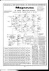
Also, I found another schematic that seems to agree with the all of the voltage readings I took yesterday, so that doesn't bother me as much anymore.
 

Attachments

  • Mag9302MSMods.jpg
    Mag9302MSMods.jpg
    72.1 KB · Views: 34
Back
Top Bottom