• The move to the new server is done. There are some software and database maintenance updates in process. This has us passing the hat around to help out. We appreciate any donations. Seriously, even a dollar helps. The payment page may be found here - https://www.audiokarma.org/support.html

Troubleshooting the Sansui AU-555A

Thank you…..Well, both fuses were blown between the output transistors. On C001,AC was approx. .025 it was a little jumpy on the meter going between 0 and .040, reading mostly in the .020’s. DC was reading 59.9. What should be my next plan of action?
DC voltage looks good. AC too.

Check the output transistors. Both fuses blown is not a good sign. Do you know how to check transistors with a DMM?
 
Last edited:
And what is some scenarios if the output transistors are bad?
Then you need to begin tracing back from the outputs to see what else may be damaged. It's helpful to print out the schematic and mark each part you find defective. It's a good way to trace the path of destruction, and helps to localize the problem. Outside of the outputs (which, can run around $5-9 each, depending on what they are) the other parts are cheap.
 
Then you need to begin tracing back from the outputs to see what else may be damaged. It's helpful to print out the schematic and mark each part you find defective. It's a good way to trace the path of destruction, and helps to localize the problem. Outside of the outputs (which, can run around $5-9 each, depending on what they are) the other parts are cheap.
All 4 transistors are good… they all get readings of approx . 520-.530
 
How would I go about this? What is the best way to build one? How would I use it to test my amp?
The way the DBT works is that it places the filament of an incandescent light bulb in series with the stereo's AC power in. Under normal operation, when you have it connected and power up the stereo you're working on the bulb will glow brightly then immediately go dim or extinguish completely. This is caused by the stereo's power supply filter capacitors charging; at first they take a lot of current, but as they charge up they take less. The whole process takes only 2-3 seconds.

On the other hand, should there be something shorted in the stereo it continues to pull current, and as the bulb's filament heats up its resistance increases and it starves the stereo of current that could cause further damage, and giving you an unmistakable indication that something's wrong.
 
You can replace the fuses and try it, but as @Leestereo said build a dim bulb tester before you do anything like that.
I built a dim bulb tester, replaced the blown fuses between the output transistors, the amp passed the dim bulb test! Replaced the fuses and it sounds great! The balance and eq pots are a little bit scratchy. Do y’all recommend Deoxit here for that? I suppose I’ll clean it up a bit and do some mods! I got real lucky on this one! I was ready to wait out in the trenches and break out the artillery…I sure learned a bunch already . Thanks everyone for your help!
 
Last edited:
I built a dim bulb tester, replaced the blown fuses between the output transistors, the amp passed the dim bulb test! Replaced the fuses and it sounds great! The balance and eq pots are a little bit scratchy. Do y’all recommend Deoxit here for that? I suppose I’ll clean it up a bit and do some mods! I got real lucky on this one! I was ready to wait out in the trenches and break out the artillery…I sure learned a bunch already . Thanks everyone for your help!
I'm still concerned as to why the amp had blown fuses. Maybe it was just driven too hard, or asked to drive too many speakers.

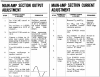
There are two adjustments that should be checked for the output stage, symmetry and bias. While you need a scope to do the symmetry, you can check the bias (referred to here as Main-Amp Section Current Adjustment) with your multimeter:

upload_2021-11-9_4-22-39.png
 
I built a dim bulb tester, replaced the blown fuses between the output transistors, the amp passed the dim bulb test! Replaced the fuses and it sounds great! The balance and eq pots are a little bit scratchy. Do y’all recommend Deoxit here for that? I suppose I’ll clean it up a bit and do some mods! I got real lucky on this one! I was ready to wait out in the trenches and break out the artillery…I sure learned a bunch already . Thanks everyone for your help!
Oh yeah, and Deoxit Faderlube F5 for pots, D5 for switches.
 
@DatGtrPlaR BTW, be EXTREMELY careful should you try to do the bias setting. May recommend replacing the pots before trying this, because if they go open you can damage your outputs. Also recommended is to take blown fuses (did you keep them?) and solder wires to each end for insertion into the fuse holders for the current measurement. I made some of these up, and soldered single banana plugs to them for my DMM. Be sure to set up for this measurement with the amp OFF, and I'd suggest waiting a few minutes for the filter caps to discharge.

This is worth checking, even if you don't adjust it, and if it's close I'd leave it alone until you start the rebuild and replace the trimmers.

I did save my fuses. I will test the bias. When you said replace the trimmers, what is that?
 
That appears to be a useful document indeed! I am curious as to what, or who, is the source of those transistor substitutions?

Those devices were substituted during a service/rebuild in August 2019. The unit work well after the service.

You may notice that there are some changed component values, and added components in several places, including the power amp, preamp, and power supply sectons. This was done as a result of implementing the accumulated upgrades during the course of production and service.
 
Last edited:
I did save my fuses. I will test the bias. When you said replace the trimmers, what is that?
I made 2 of these:

Sansui fuse adapter.jpg

You plug these into the current input on your DMM. All the current that would normally flow through the fuse now flows through you meter, showing you how much current the output stage is drawing.. Much safer using these; one slip with a probe while making this measurement can cause serious damage.
 
I will try this. I guess the broken filaments in blown fuses shouldn’t be an issue with this. And I would have to mindful or the direction of current I’m measuring? The fuses between the output transistors, one for left and right channels I assume?
 
I will try this. I guess the broken filaments in blown fuses shouldn’t be an issue with this. And I would have to mindful or the direction of current I’m measuring? The fuses between the output transistors, one for left and right channels I assume?
Yes. If it reads negative you can just swap the leads at the meter. It doesn't really matter with a digital meter; you're not pegging a needle to the left on an analog meter.

Filaments aren't a problem, since they're blown.
 
@DatGtrPlaR BTW, be EXTREMELY careful should you try to do the bias setting. May recommend replacing the pots before trying this, because if they go open you can damage your outputs. Also recommended is to take blown fuses (did you keep them?) and solder wires to each end for insertion into the fuse holders for the current measurement. I made some of these up, and soldered single banana plugs to them for my DMM. Be sure to set up for this measurement with the amp OFF, and I'd suggest waiting a few minutes for the filter caps to discharge.

This is worth checking, even if you don't adjust it, and if it's close I'd leave it alone until you start the rebuild and replace the trimmers.

I have soldered banana plugs to the fuses, as you recommended. Should I measure both fuses points with two meters at the same time? And should I have any input going into the amp as I’m testing it when it is turned on, or does that not matter? Also, I was able to acquire a 2445A from fleabay for 150$ currently on its way.
 
Back
Top Bottom