• The move to the new server is done. There are some software and database maintenance updates in process. This has us passing the hat around to help out. We appreciate any donations. Seriously, even a dollar helps. The payment page may be found here - https://www.audiokarma.org/support.html

Troubleshooting Yamaha C-70 power supply

elias_a

New Member
Hi,

A newbie from Finland salutes you all with golden ear!

I bought years ago a C-70 that had "minor flaws". In practice this means the unit makes a buzzing sound after powering on, not to output but physically audible buzz. The sound fades after few minutes.

Before yesterday I have not had access to proper oscilloscope but now I have tools for troubleshooting and I am trying to cope with the learning

According to C-70 Service Manual the power unit gives following DC voltages:

+ 33 V
- 33 V
+16 V
-16 V

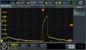
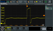
The +/- 33 VDC are stable. There are problems with both the +16V and the supposedly +24 VDC to operate the relays. Both have a 100 Hz anomaly that explains why the buzzing sound occurs after powering on: relay RY101 vibrates making a 200 Hz sound.

This is what the 24 VDC looks like when measured from the opering voltage pin of RY101:
C-70_24V.png

The 16 VDC has also problems. This is measured from the yellow wire soldered close to RY101 with text MUTE +16 SD1 on the component side of the PCB. The GND of the probe has been connected to the outer ring of RCA connector connected to the same PCB.
C-70_16V.png

I cannot figure out where the +/- 16 VDC and 24 VDC are generated in the power supply. Any hints how to proceed?

The unit has been serviced by someone at some stage. At least capacitors C596 and C597 have been changed to Rubycon 10 000 uF 50V 85 Celsius capacitors and some other capacitors too. I have visually inspected the soldering of all components that look like they have been changed. I have not found any solder bridges or cold joints that would explain anything.
 
Register to hide this ad
I recommend getting a service manual and following the schematic to figure out how the power supply works (Hifi engine or Analog alley). Verify what components are in there if some previous work has been done. I would bet a transistor in the power supply is likely going bad. Check for cracks on the PCB, damage from glue on components that started to corrode.
 
I recommend getting a service manual and following the schematic to figure out how the power supply works (Hifi engine or Analog alley). Verify what components are in there if some previous work has been done. I would bet a transistor in the power supply is likely going bad. Check for cracks on the PCB, damage from glue on components that started to corrode.
I do have the service manual. My skills are so limited that I cannot figure out how the power supply works. :/
 
I do have the service manual. My skills are so limited that I cannot figure out how the power supply works. :/
Ok, I looked at it briefly this morning. It looks like there are two different rectifiers, so different paths that the unit makes DC from AC. Follow the connections where the DC that you are concerned about backwards and you will see which components might be causing the issue. I have a C-70, but probably can't get to this until this weekend.
 
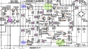
In the following screenshot, the light green circles are your regulated +/-33VDC. The light purple circles are the regulated +/-17VDC for most ICs, and the light pink circle to the left is your regulated +30VDC.

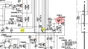
In the second screenshot, the light red circle is your regulated +16VDC.

Ignore all other circles containing caps, those are for my own reference.

Check the solder work on all your relays and reflow even if they look okay. It’s possible the relay in question needs to be replaced, these are notorious for going bad.


I’m not sure why C596 and C597 would be changed to 10000uF, seems excessive. I changed mine to Nichicon Superthroughs 1000uF 63V.

IMG_2989.png

IMG_2988.png
 
I changed mine to Nichicon Superthroughs 1000uF 63V.
I went a little different route. Due to there physical location. These are nestled in between the two major heat sources. The power transformer and the two regulated supply "pass" transistors.

High temp---------- Nichicon UBX or UBY


The power transformer generates the most heat. Thats why the case has ventilation vents directly above the transformer.
 
Last edited:
I went a little different route. Due to there physical location. These are nestled in between the two major heat sources. The power transformer and the two regulated supply "pass" transistors.

High temp---------- Nichicon UBX or UBY


The power transformer generates the most heat. Thats why the case has ventilation vents directly above the transformer.
Totally agree captain, if I had UBXs on hand, they’d be in there already. Those caps are locked in a death trap. The Superthroughs were there from an earlier project so I used them. Only thing, I’m not sure if UBX caps are for audio applications, I thought they were for automotive use? I’ll pick up a few shortly anyway. I just finished moving house so everything is in boxes …

Yes, that transformer is a little heater, so I placed a low RPM fan (600rpm) directly above it and plugged into the switched AC outlet in the back of C-70. It makes a very noticeable difference, the unit runs cooler. Any higher rpm and you’ll end up hearing its noise.
 
Is your mains 50 or 60hz?
50 Hz as in all European countries. Therefore it is very likely that the resonance is caused by a problem in the power unit.

I'm making wire wrapper/unwrapper tool to get the transformer wires detached from the PCB. After that I'll measure the transformer because measured from the connections on PCB the AC is skewed.

Never seen a transformer broken like that but hey - this is fault finding! :pRigolDS0.png
 
Too late. I unwrapped them already. Lets see how I cope with wrapping them back.
Wrapping the wires back onto a previously unwrapped wire post is not recommended. When the post was originally wrapped, the sharp corners of the square cross section post bit into the wire and and a gas tight seal formed between the wire and the post's sharp corners. You won't get that the second tie around, so I reccomend soldering the replacement wire. Oxidation will eventually compromise the connection between the wire & the re-wrapped post.
 
Wrapping the wires back onto a previously unwrapped wire post is not recommended. When the post was originally wrapped, the sharp corners of the square cross section post bit into the wire and and a gas tight seal formed between the wire and the post's sharp corners. You won't get that the second tie around, so I reccomend soldering the replacement wire. Oxidation will eventually compromise the connection between the wire & the re-wrapped post.
Thank you for your good advice!

Is there some kind of active substance in the wire making the seal? I did not notice anything special in the wire. Never wrapped before and I don't think I will in the future either... :)
 
Thank you for your good advice!

Is there some kind of active substance in the wire making the seal? I did not notice anything special in the wire. Never wrapped before and I don't think I will in the future either... :)
No special ingredient in the wire or the post. If the two metals are crunched into each other at a high pressure, which is present at the sharp corners of the post, then a gas-tight seal forms between the wire and the post, keeping out air which would oxidize the metal with its oxygen content. Of course, single stand, not stranded wire must be used for this type of connection.
 
No special ingredient in the wire or the post. If the two metals are crunched into each other at a high pressure, which is present at the sharp corners of the post, then a gas-tight seal forms between the wire and the post, keeping out air which would oxidize the metal with its oxygen content. Of course, single stand, not stranded wire must be used for this type of connection.

I see. In this case the wires were all braided wire.
 
Back
Top Bottom