• The move to the new server is done. There are some software and database maintenance updates in process. This has us passing the hat around to help out. We appreciate any donations. Seriously, even a dollar helps. The payment page may be found here - https://www.audiokarma.org/support.html

Trying to repair a Marantz 1090

DI(wh)Y

New Member
Hi everyone

I am trying to repair/restore a Marantz 1090.

My name is Diego, I am from Switzerland, and have some experience in electrical engineering. But I am a total noob when it comes to Hi-Fi audio and to repairing vintage audio electronics.

A few month ago my niece wished to get a turntable for her birthday. After a bit of web search and based on her style preference I bought a Dual 1090 and restored it for her. Due to this I rediscovered the joy to deliberatly listen to music again and additionally got infected a bit by the vintage "Hi-Fi" virus.

Long story short: I recently bought a Marantz 1090 sold as "not working/unknown". On the first test I quickly noticed that PreOut must be connected to MainIn externally (as obviously on many old Marantz'). However, with that bridge in place, the amplifier seems to work mostly fine and sounds great (in humble opinion based on my - yet - untrained ears): Tuner/Aux/Tape 1/2 inputs work, the tone control and balance work, HiFilter, Mono, Out/In/Loudness selection work.

However, the Phono 1/Phono 2 inputs do not work. And based on what I read about vintage audio restoration I maybe also want to change some capacitors etc.
And when i looked at the boards and the service manual i ran into a few questions that I hope some of you, giants, can help me with.

My current plan is as follows:
- Repair phone pre-amp
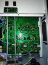
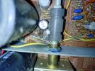
- Check and eventually repair section around Q803, R802, R803 (looks burned)
- Check and eventually replace electrolytic caps

- Should I do more? I read on Leestereo's thread that changing "capacitors in the signal path" and maybe even diodes and some (?) resistors may be beneficial? And how important do you consider changing the heatpast on the power transistors? - The heatpaste on the edge of the cases is still "creamy", should i change it anyway?

The questions I currently wonder most about are:
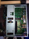
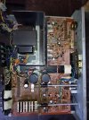
- Is it normal that so many capacitors are placed on the bottom side? Is this somehow reflected in the schematic in the service manual?
- 3 traces on the bottom side of the Pre-Amp-PCB are cut (intentionally it seems). Is that normal? What could have been the motivation?

I hope some of you can help and guide me on this repair and I am really looking foreward to your feedback.
Best regards
Diego % DI(wh)Y
 

Attachments

  • Top_All_BurntSectionMarked.JPG
    Top_All_BurntSectionMarked.JPG
    160.2 KB · Views: 40
  • Bottom_PreampPCB_CutTracesMarked.JPG
    Bottom_PreampPCB_CutTracesMarked.JPG
    159 KB · Views: 40
  • Bottom_All.JPG
    Bottom_All.JPG
    137 KB · Views: 35
  • Top_BurntSectionOnly.JPG
    Top_BurntSectionOnly.JPG
    136 KB · Views: 38
Register to hide this ad
That thing is 50 years old. Don't bother testing them, just replace ALL electrolytic caps. You might find the phono preamp starts working with new caps, and if it doesn't, you'll know that the problem isn't the caps and can continue to troubleshoot.
 
Yeah, replace all electrolytic caps! Also replace any fuse resistors. Look closely at the board for any discoloration on the PCB, that's usually a tell tale of parts that live a hard life, and may be out of spec. Reflow any solder joint that looks suspect. Don't forget to check the bias after, it most likely will be off.

If there are a couple bad caps, it will sound so much better after, as mrehorst said, everything might just work as it should after.
 
Thank you very much for these first inputs. Thus my new plan is:
- Replace all electrolytic caps
- Check solder joints and eventually reflow/resolder
- Check and eventually repair section around Q803, R802, R803 (looks burned, could not find any other discoloration on the PCB or on the top cover): I Checked the voltages and the C806 is on +28 instead of +38V. So i guess the problem is the +38V supply for the phono-pre-amp, rather than the preamp itself.
- Check bias of main amp
- Then see if phone-pre-amp works.

Any inputs on the "cut traces" or on the capacitors mounted on the bottom side?

Thank you and best regards
Diego
 
Thank you very much for these first inputs. Thus my new plan is:
- Replace all electrolytic caps
- Check solder joints and eventually reflow/resolder
- Check and eventually repair section around Q803, R802, R803 (looks burned, could not find any other discoloration on the PCB or on the top cover): I Checked the voltages and the C806 is on +28 instead of +38V. So i guess the problem is the +38V supply for the phono-pre-amp, rather than the preamp itself.
- Check bias of main amp
- Then see if phone-pre-amp works.

Any inputs on the "cut traces" or on the capacitors mounted on the bottom side?

Thank you and best regards
Diego
Good plan, also forgot to say, replace any carbon comp resistor.
Find out why they are cut, is it factory, an update, or some ham fisted repair?
There are a couple reasons why things are on the bottom of a board, one to attach 2 points that are not on the PCB, a part that is also a jumper. The other is to get the proper value say we need 33uf, used a 22uf on top and a 10uf on the bottom. If that is the case, just try to get a 33uf cap, put on top, with nothing on the bottom.
 
Thank you very much for these first inputs. Thus my new plan is:
- Replace all electrolytic caps
My current plan is as follows:
- Repair phone pre-amp
- Check and eventually repair section around Q803, R802, R803 (looks burned)
- Check and eventually replace electrolytic caps
My feeling is that your original plan is a better one. Fix the known problem areas first to get the amp fully functional again, then replace worn caps one board at a time, test, then move on to the next board. Do it this way and it will be easier to isolate any issues that may arise since you only changed parts on the board being worked on and not the whole amp.
 
My feeling is that your original plan is a better one. Fix the known problem areas first to get the amp fully functional again, then replace worn caps one board at a time, test, then move on to the next board. Do it this way and it will be easier to isolate any issues that may arise since you only changed parts on the board being worked on and not the whole amp.
It's never going to be fully functional if the electrolytic caps are bad. You're going to have to replace all of them anyway, so doing it first makes the most sense.

Let's say you start with the phono preamp stage. How do you get it working? You start by replacing the electrolytic caps in that stage. Does it work? No? OK, maybe it's the power supply caps. You replace the caps in the power supply to get the phono stage working. Does it work now? No? It could be semiconductors in the phono preamp or it could be it's the caps in the power amp that are the problem. You replace the caps in the power amp. Does it work now? No? Maybe some of the semiconductors are dead. Now you can start locating the bad ones and replacing them as needed until the thing works, knowing that the problem isn't the caps.

Just replace all the electrolytics first and you can immediately and completely rule out one very common potential source of trouble for the entire device.
 
However, with that bridge in place, the amplifier seems to work mostly fine and sounds great (in humble opinion based on my - yet - untrained ears): Tuner/Aux/Tape 1/2 inputs work, the tone control and balance work, HiFilter, Mono, Out/In/Loudness selection work.

However, the Phono 1/Phono 2 inputs do not work.
@mrehorst, my recommendation was based on the OP's description above. Everything works except for the Phono 1 and Phono 2 inputs (P400). After troubleshooting the Phono inputs and getting a functional amp, then he can start replacing components one board at a time. It may be that the power supply voltage to the phone preamp is bad, but at least you follow the path of voltages to the source of the problem. But, the OP can do whatever he wants to. ;)
 
Thank you very much for these first inputs. Thus my new plan is:
- Replace all electrolytic caps
- Check solder joints and eventually reflow/resolder
- Check and eventually repair section around Q803, R802, R803 (looks burned, could not find any other discoloration on the PCB or on the top cover): I Checked the voltages and the C806 is on +28 instead of +38V. So i guess the problem is the +38V supply for the phono-pre-amp, rather than the preamp itself.
- Check bias of main amp
- Then see if phone-pre-amp works.

Any inputs on the "cut traces" or on the capacitors mounted on the bottom side?

Thank you and best regards
Diego
Get the power supply fixed first.
 
Hi all

Thank you so much for all your inputs and sorry for beeing late with an updat. Currently I am on Ski-holiday and thus i cannot really work on the Amp this week.
Anyway, I enjoy reading your inputs and try to prepare for the next round of soldering by ordering some caps etc that I may (or may not) have to replace.

Last Friday i desoldered some of the components around the +38V supply. As mentioned, Q803, R802, R803 looked burned and i thought some or all of these components are defect. However, it turned out, that only C804 was defective (shorted). Unfortunately I did not have a spare cap to test if this alone would fix the preamp. So I really look foreward to trying to replace C804. I noticed that Q803 (2SC1407) had a bit a low hfe (about 70 only). Would you replace this BJT too or do you think this is still ok/within spec?

Based on your inputs and reading other comments about the "shotgun" approach to recapping I will definitely first try to "fully fix" the amp. During this i will check the capacitance and ESR values of all electorlytic caps and change those that are faulty. Then later if the amp works again i will think about fully recapping section by section.
As outlined by Dankik, the main amplifier works, just as tape in, aux in, equalizer etc. So I think i will be possible to monitor progress using a multimeter, oscilloscope and my ears. Hopefully.

By the way I refer to the service manual scanned by Peter Vis:

Regarding the capacitors i plan to order the following types:
- For the "bigger" electrolytic caps i plan to use Nichicon UKW series if i find an appropriate match. Or would you recommand another series?
- For the "smaller" (orange) electrolytic caps I am even less sure. Some of these are as far as i understood this "in the signal path" (like C421, C422 at the output of the phono preamp: 2.2uF, 35V ). Should I rather use "bipolar" caps of some specific type or brand in this case?

I will probably also order a few replacement BJTs, but i still need a bit (a lot) of time to find "potentially appropriate" replacement parts for many of those. So if you have some hints about which ones often fail, become "noisy" or similar, that would be great too!

Any further input is highly appreciated. I'll keep you updated...

Thank you very much already!
Best regards,
Diego
 
Hi all

Thank you so much for all your inputs and sorry for beeing late with an updat. Currently I am on Ski-holiday and thus i cannot really work on the Amp this week.
Anyway, I enjoy reading your inputs and try to prepare for the next round of soldering by ordering some caps etc that I may (or may not) have to replace.

Last Friday i desoldered some of the components around the +38V supply. As mentioned, Q803, R802, R803 looked burned and i thought some or all of these components are defect. However, it turned out, that only C804 was defective (shorted). Unfortunately I did not have a spare cap to test if this alone would fix the preamp. So I really look foreward to trying to replace C804. I noticed that Q803 (2SC1407) had a bit a low hfe (about 70 only). Would you replace this BJT too or do you think this is still ok/within spec?

Based on your inputs and reading other comments about the "shotgun" approach to recapping I will definitely first try to "fully fix" the amp. During this i will check the capacitance and ESR values of all electorlytic caps and change those that are faulty. Then later if the amp works again i will think about fully recapping section by section.
As outlined by Dankik, the main amplifier works, just as tape in, aux in, equalizer etc. So I think i will be possible to monitor progress using a multimeter, oscilloscope and my ears. Hopefully.

By the way I refer to the service manual scanned by Peter Vis:

Regarding the capacitors i plan to order the following types:
- For the "bigger" electrolytic caps i plan to use Nichicon UKW series if i find an appropriate match. Or would you recommand another series?
- For the "smaller" (orange) electrolytic caps I am even less sure. Some of these are as far as i understood this "in the signal path" (like C421, C422 at the output of the phono preamp: 2.2uF, 35V ). Should I rather use "bipolar" caps of some specific type or brand in this case?

I will probably also order a few replacement BJTs, but i still need a bit (a lot) of time to find "potentially appropriate" replacement parts for many of those. So if you have some hints about which ones often fail, become "noisy" or similar, that would be great too!

Any further input is highly appreciated. I'll keep you updated...

Thank you very much already!
Best regards,
Diego
No to the UKW. Use UPW/UVZ/similar.
Orange caps use UKL or film. Do not use bipolar ever unless the cap you’re replacing is bipolar!

Buy a bunch of KSC1845 and KSA992. That will be the majority you need.

In my restores, I replace all transistors
 
No to the UKW. Use UPW/UVZ/similar.
Orange caps use UKL or film. Do not use bipolar ever unless the cap you’re replacing is bipolar!

Buy a bunch of KSC1845 and KSA992. That will be the majority you need.

In my restores, I replace all transistors
Dear ivandezande

Thank you very much for that clear recommendation!

Regarding the UKL, i already had a tendency for this series to replace the "orange caps" based on the discussion here: https://audiokarma.org/forums/index.php?threads/best-nichicon-series-to-use.732762/

Could you kindly outline why not to use UKW but rather UPW/UVZ/similar?

I guess the UPW are better suited for power supply purposes (even non-SMPS) as they feature a lower ESR (?) and much higher reliability/lifetime than the UKW. Are these the main factors motivating your choice?
And why are UVZ better than UKW for this purpose? Based on the discussion mentioned i would have thought that UKT, UKA, UFG, UKZ (and UKW) would be better. What did i get wrong there?

I am really looking foreward to your answer.
Best regards
 
Dear ivandezande

Thank you very much for that clear recommendation!

Regarding the UKL, i already had a tendency for this series to replace the "orange caps" based on the discussion here: https://audiokarma.org/forums/index.php?threads/best-nichicon-series-to-use.732762/

Could you kindly outline why not to use UKW but rather UPW/UVZ/similar?

I guess the UPW are better suited for power supply purposes (even non-SMPS) as they feature a lower ESR (?) and much higher reliability/lifetime than the UKW. Are these the main factors motivating your choice?
And why are UVZ better than UKW for this purpose? Based on the discussion mentioned i would have thought that UKT, UKA, UFG, UKZ (and UKW) would be better. What did i get wrong there?

I am really looking foreward to your answer.
Best regards
I don't believe in "audio" caps and their prices. I'd rather use a long life cap or a standard high temp cap. Lots more size/voltage/capacitance options there still as opposed to the "audio" lines.

But follow your heart, any new caps are going to be better than the old at least.

I just finished a restore of a 1090 yesterday. They sound good.
 
To all of you who replied to my questions and the entire Audiokarma Community

I kind of love you. So much support and wisdom - Thank you very much!

TLDR: All electrolytic caps repaced. Everything works fine and sounds great in my untrained ears. And i learned quite a bit..more below :)

The longer story....
Last week I finally had time and the capacitors to continue my journey with the 1090.

First of all, i replaced C806 and checked the voltage of the +38V supply line again. And indeed, it now was at +38V as it should. Unfortunately i did not yet have a turntable to test the phono inputs. So i googled a bit and just gave it a try with my mobile phone: So I connected the mobile with a jack-to-cinch cable to the 1090, turned the phone's volume down to the minimum and turned on the 1090. And, hurray, there was sound. Quite a bit "dull" due to the preamp's RIAA equalization but it clearly indicated that the phono preamp worked. Great. Lucky so far...?

As proposed by many of you, I subsequently wanted to replace the other electrolytic capacitors. But as countless experts point out, a Dimm-Bulb Tester can be priceless in case of stupid mistakes or other errors. So I first built one using an old mains/extension cord, a bulb socket and a switch i had laying around. I connected the amp to it, turned on the power and the bulb behaved as expected: Short bright flash at the start for half second or so, subsequently a rather dim glow. I should note that i had connected a pair of cheap speakers to the amp to test it as i was scared i might ruin some speakers in case of a problem.
Anyway, I unplugged the mains power, and checked the residual voltage on the big power supply caps (C802, C809, C810). Obviously these caps get discharged within a few seconds if the power to the amp is cut while the amp's power switch is still on and if speakers are connected to it. So i went ahead and removed these caps. This was a bit of fuzz since they were glued on quite well and because the solder joints are a bit hard to reach if the pcb is not removed from the metal frame (especially C802). I took a bit of time to remove the old glue and also to clean most of the pcb a little with some isoprop alcohol. Then I mounted the replacement caps and plugged in mains again. Initially all seemd fine: Short flash followed by weak glow. Until this point, the speakers turned on about 5 seconds after powering the 1090. However, this time the speakers just made a short click after a few seconds and the dim bulb flashed up again. Of course, i immediately cut the power. I inspected the pcbs and could not find a mistake. Powered back on, same behaviour, a bit more courage, left it running and noticed that the "crackling noise + bulb flash" repeated every few seconds. Too bad.

Well, everyone makes mistakes occasionally. I inspected the pcb, the orientation of the supply caps etc but i could not find a problem. Did i order the wrong caps? The specs seemed fine...sufficient capacity and voltage rating. Anyway, that was my last change so the problem must be there i guessed. I cursed a bit and bit the sour apple. I unsoldered the new caps and mounted the old ones again. Same behavior. However, when i changed the source to Aux, at least the repeting dim-bulb flash disappeared. So I checked the voltage on the +38V rail as this was the only other part i had modified and as it was broken initially. And to my surprise it was back at about 29V only. Well i guess something else of this supply or loading it must have given way and broke, i thought. Maybe due to the new caps with a lower ESR or whatever... So i disconnected the cables going to the main amp (being the only load). Still only 29V. I checked the voltage at the output of the rectifier (Q801/Q802): far too low as well. Just as the voltage coming from the transformer. WTF. Is there still a kinda-short pulling down these voltages? Could hardly imagine that... Did I damage the transformer? That would be too bad. I thought about it about an hour but i just could not figure what the problem may be. As you can imagine I was quite sad at this point and a bit annoyed at myself for trying to "fix something that aint broke". The amplifier worked completely and sounded great - why o why did i have to mess with it. As it was already quite late i went to bed. And then, suddenly, it fell like scales from my eyes. You attentive readers and experts have probably noticed my mistake long ago: I still had the amp connected to the dim bulb tester. So i got back up, connected the amp directly to mains and, voila, the voltage on the rectifier was at 44V as it should. Stupid beginners mistake...

The next day i repopulated the 38V-supply section with all new caps. First, i checked the operation with the dim-bulb that indicated no major problem. Subsequently, I measured the voltage without dim-bulb and it was back at +38V. Hurray.
I then continued to change the other electrolytic caps section by section and tested the operation after every section. And finally i replaced the old supply caps with the new ones, a second time. And everything still worked, sounded, and measured fine. I also checked the bias voltages (without dim-bulb :)) and readjusted it to about 12mV after a few minuts (I will recheck the setting again in the upcoming weeks)

Yesterday, I could finally connect an old Dual 1219 to the phono input and indeed, the phono preamp works well too.

Some notes that may be interesting for some of you giants or other beginners like me:
- I did not find any other capacitor (except C806) that was/seems actually defect. They all had a capacitance within +-20% of their spec and the ESR values also seemed reasonable. Surprising after all these years. Maybe the amp was just on the shelf for most of its life...?
- I think the "cut traces" are in fact factory made. On a thread, "Hirscwi" posted an image of the bottom side of his 1090's main amp pcb and there seems to be a cut in (at least) one of the locations as on my PCB. However, his pcb obviously has a slightly different layout and the cut is covered by laquer. See the post of Mar 30 in this thread: https://audiokarma.org/forums/index...o-marantz-1090-revisited.584735/#post-7695246
It may be worth to note, that the layout of my pcb also differs a bit from the layout in the service manual scanned by Peter Vis.


So this is where i am at.
Now I still see a few things to do and would highly appreciate your advice regarding the following questions:
  • Should i change the capacitors in the mains supply lines (C003 and C004, Oil-paper cap, 0.022uF 450V AC, axial)? If yes: would
    PPA2202220KJ be a good choice?
  • Should i really replace some/all bipolar transistors and/or other components?
  • Should i do something else additionally?

Very best regards and THANK YOU.
 
So this is where i am at.
Now I still see a few things to do and would highly appreciate your advice regarding the following questions:
  • Should i change the capacitors in the mains supply lines (C003 and C004, Oil-paper cap, 0.022uF 450V AC, axial)? If yes: would
    PPA2202220KJ be a good choice?
  • Should i really replace some/all bipolar transistors and/or other components?
  • Should i do something else additionally?
LOL, on the dim bulb, it will create a voltage drop! Think we all have been bit by that. Same for adjusting settings under dim bulb. My new practice is to measure bias and other adjustments before changing anything. Then adjust the trims all the way down before replacing parts. Think we all have also mounted a transistor and/or cap the wrong way. One time I spent 8hrs tracking down a no power issue, that was a lifted resistor lead.

Usually while you are in there, replace all electrolytic caps. The only time I do not is when they are big supply caps, that are either hard to get or cost more than the unit. However, this is also after testing to make sure they are "in spec"
Measure the oil cap, decide after, not sure if you should replace with same, or something else.
If the transistors are on the "bad" list, it's worth changing them. But if your unit works just fine, maybe do them later.
If there are any carbon composition or fuse resistors, replace them.

Also, redo your bias after a bit of run in.

Congrats on your recap!
 
To all of you who replied to my questions and the entire Audiokarma Community

I kind of love you. So much support and wisdom - Thank you very much!

TLDR: All electrolytic caps repaced. Everything works fine and sounds great in my untrained ears. And i learned quite a bit..more below :)

The longer story....
Last week I finally had time and the capacitors to continue my journey with the 1090.

First of all, i replaced C806 and checked the voltage of the +38V supply line again. And indeed, it now was at +38V as it should. Unfortunately i did not yet have a turntable to test the phono inputs. So i googled a bit and just gave it a try with my mobile phone: So I connected the mobile with a jack-to-cinch cable to the 1090, turned the phone's volume down to the minimum and turned on the 1090. And, hurray, there was sound. Quite a bit "dull" due to the preamp's RIAA equalization but it clearly indicated that the phono preamp worked. Great. Lucky so far...?

As proposed by many of you, I subsequently wanted to replace the other electrolytic capacitors. But as countless experts point out, a Dimm-Bulb Tester can be priceless in case of stupid mistakes or other errors. So I first built one using an old mains/extension cord, a bulb socket and a switch i had laying around. I connected the amp to it, turned on the power and the bulb behaved as expected: Short bright flash at the start for half second or so, subsequently a rather dim glow. I should note that i had connected a pair of cheap speakers to the amp to test it as i was scared i might ruin some speakers in case of a problem.
Anyway, I unplugged the mains power, and checked the residual voltage on the big power supply caps (C802, C809, C810). Obviously these caps get discharged within a few seconds if the power to the amp is cut while the amp's power switch is still on and if speakers are connected to it. So i went ahead and removed these caps. This was a bit of fuzz since they were glued on quite well and because the solder joints are a bit hard to reach if the pcb is not removed from the metal frame (especially C802). I took a bit of time to remove the old glue and also to clean most of the pcb a little with some isoprop alcohol. Then I mounted the replacement caps and plugged in mains again. Initially all seemd fine: Short flash followed by weak glow. Until this point, the speakers turned on about 5 seconds after powering the 1090. However, this time the speakers just made a short click after a few seconds and the dim bulb flashed up again. Of course, i immediately cut the power. I inspected the pcbs and could not find a mistake. Powered back on, same behaviour, a bit more courage, left it running and noticed that the "crackling noise + bulb flash" repeated every few seconds. Too bad.

Well, everyone makes mistakes occasionally. I inspected the pcb, the orientation of the supply caps etc but i could not find a problem. Did i order the wrong caps? The specs seemed fine...sufficient capacity and voltage rating. Anyway, that was my last change so the problem must be there i guessed. I cursed a bit and bit the sour apple. I unsoldered the new caps and mounted the old ones again. Same behavior. However, when i changed the source to Aux, at least the repeting dim-bulb flash disappeared. So I checked the voltage on the +38V rail as this was the only other part i had modified and as it was broken initially. And to my surprise it was back at about 29V only. Well i guess something else of this supply or loading it must have given way and broke, i thought. Maybe due to the new caps with a lower ESR or whatever... So i disconnected the cables going to the main amp (being the only load). Still only 29V. I checked the voltage at the output of the rectifier (Q801/Q802): far too low as well. Just as the voltage coming from the transformer. WTF. Is there still a kinda-short pulling down these voltages? Could hardly imagine that... Did I damage the transformer? That would be too bad. I thought about it about an hour but i just could not figure what the problem may be. As you can imagine I was quite sad at this point and a bit annoyed at myself for trying to "fix something that aint broke". The amplifier worked completely and sounded great - why o why did i have to mess with it. As it was already quite late i went to bed. And then, suddenly, it fell like scales from my eyes. You attentive readers and experts have probably noticed my mistake long ago: I still had the amp connected to the dim bulb tester. So i got back up, connected the amp directly to mains and, voila, the voltage on the rectifier was at 44V as it should. Stupid beginners mistake...

The next day i repopulated the 38V-supply section with all new caps. First, i checked the operation with the dim-bulb that indicated no major problem. Subsequently, I measured the voltage without dim-bulb and it was back at +38V. Hurray.
I then continued to change the other electrolytic caps section by section and tested the operation after every section. And finally i replaced the old supply caps with the new ones, a second time. And everything still worked, sounded, and measured fine. I also checked the bias voltages (without dim-bulb :)) and readjusted it to about 12mV after a few minuts (I will recheck the setting again in the upcoming weeks)

Yesterday, I could finally connect an old Dual 1219 to the phono input and indeed, the phono preamp works well too.

Some notes that may be interesting for some of you giants or other beginners like me:
- I did not find any other capacitor (except C806) that was/seems actually defect. They all had a capacitance within +-20% of their spec and the ESR values also seemed reasonable. Surprising after all these years. Maybe the amp was just on the shelf for most of its life...?
- I think the "cut traces" are in fact factory made. On a thread, "Hirscwi" posted an image of the bottom side of his 1090's main amp pcb and there seems to be a cut in (at least) one of the locations as on my PCB. However, his pcb obviously has a slightly different layout and the cut is covered by laquer. See the post of Mar 30 in this thread: https://audiokarma.org/forums/index...o-marantz-1090-revisited.584735/#post-7695246
It may be worth to note, that the layout of my pcb also differs a bit from the layout in the service manual scanned by Peter Vis.


So this is where i am at.
Now I still see a few things to do and would highly appreciate your advice regarding the following questions:
  • Should i change the capacitors in the mains supply lines (C003 and C004, Oil-paper cap, 0.022uF 450V AC, axial)? If yes: would
    PPA2202220KJ be a good choice?
  • Should i really replace some/all bipolar transistors and/or other components?
  • Should i do something else additionally?

Very best regards and THANK YOU.
1: Yes, no, not a good choice. The cap has to be Class X rated (line to line) or Class Y rated (line to earth)
2: All small signal. They will all get noisy/leaky or fail.
3: No.
 
Back
Top Bottom