• The move to the new server is done. There are some software and database maintenance updates in process. This has us passing the hat around to help out. We appreciate any donations. Seriously, even a dollar helps. The payment page may be found here - https://www.audiokarma.org/support.html

Tube Amp build exercise using Fisher Philharmonic V 29T Transformers

grindfix

Full time hobby
Subscriber
This is a continuation of the thread I started with a question about using different output tubes to replace ELL80. Out of all possible contenders I only have (plenty of) 6BQ5 tubes, so I decided to give it a try.
Amp was quickly knocked together using Allen organ PS chassis with no cosmetic goals in mind.

I copied driver / inverter stage from 29T schematic, modified PS and bias circuits, added individual bias adjustment, screen resistors, and DC elevated heater windings (there's one individual per channel).
I get around 315v B+ rail. Output tubes are biased at 22mA of cathode current and amp produces around 13wpc into 8ohm with both channels driven. With the original NFB network values, I get 14dB of applied feedback. Frequency response looks decent at 1w, square waves look good. The amp seems to be very stable and I couldn't find a load combination to upset it. I haven't tried to increase the feedback level yet.
Input sensitivity is around 390mv.
All looks promising except one issue. At full power and even significantly below it, wheels are falling off the wagon below the 60Hz mark. At first, I thought that it was OT saturation but after seeing similar results at lower power levels I scoped inverter output and it shows a similar scope pattern that I see on output terminals.
I took series of scope screenshots, including inverter outputs.
Does it appear that the driver stage runs out of steam? The famed "noose"?

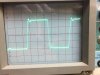
Here is 1KHz square:

1KHz.jpeg


8KHz:

8KHz.jpeg


Here is what's happening across dummy loads:

Below 50Hz.jpeg


Here is the inverter output simultaneously:

PI output.jpeg


And here is the schematic:

Schematic.jpeg
 
Register to hide this ad
unhook the feedback and see if the inverter output looks normal. If the transformers are giving up at 60, you'll get a mangled waveform back through the NFB connection and that will make the inverter output look screwy. This won't do anything to fix the transformer saturation but it will at least isolate the issue.
 
Duh! Sure enough. I'll never ask this question again!

So, it's not the inverter stage, but those transformers saturate at much lower power levels.
Reducing power allows lower frequency before it starts to saturate OT but not to the acceptable response levels. For example, at full power, I will see the scope pattern distort below 60Hz.
At 1dB down from full power visual trace distortion sets around 50Hz.
At 1 watt I can see this saturation below 35Hz.

Gadget, have you done any scope measurements of your 29T? What does your LF pattern look like?
I wonder if the 2k lower plate to plate requirement of 6BQ5 vs. ELL80/6HU8 plays a role in this saturation?

I think this thread should have been posted in Tube Forum instead. How can I have it moved?
 
Click REPORT at bottom of your post, and ask moderator to move the thread to tube forum.
 
OK, now we know its transformers. How well do your output tubes match? A significant idle current mismatch will cause saturation at higher frequencies than it would otherwise. Ideally they should also be matched under working conditions too but the idle current mismatch will show up at low power levels. If they're decently matched, that just might be all the iron has to give. Its not a powerhouse and those transformers aren't massive.


I've never measured anything on my 29T. Actually the only thing I ever did to it was replace the two voltage doubler caps and give it an adjustable bias setup. The cans and the rest of it are as-built. Basically I got it to play, it sounded OK and I left it on my "round tuit" list.
 
Tubes are tested very close on my 533 and biased at 22ma with adjustable bias. One thing I haven't measured is how close the negative grid voltage is between the tubes at 22mA.

If you ever get yours on the bench, would be interesting to see how transformers perform in the original environment. I couldn't do that because the original output tubes were very unbalanced by the tube tester. I measured bias voltage at each grid and it was all over the place so I knew couplings were leaking and wore tubes out. Plus, the screen resistor was replaced with an underrated one by someone with poor soldering skills and it was blown into 2 pieces. Replacement got the amp working but I didn't want to risk the transformers and never powered it on again.
 
It's too bad that the transformers don't have a 16 ohm tap.

If they did- I would suggest using something like a 6Y6 or EL86/6CW5, with a lower B+ voltage (about 225 to 250V), and run an 8 ohm load on the 16 ohm tap. Make the transformers act more like a 4600 ohm primary- which is OK for 6Y6s or EL86s.

Half- impedance mode would probably improve the low-end output quite a bit- I've seen transformers go close to an octave lower before saturation, under these conditions. The HF response takes a bit of a hit, as the trade-off- but that's something that usually can be dealt with with feedback tuning...

Regards,
Gordon.
 
So, as I understand, I need to select a pair that wants more than 10k Raa to perform better with these 10.25k primary transformers.
Telefunken ELL80 (original in 29T I believe) shows 11k. What other pentodes or tetrodes fall into that range or higher? I'm not looking to get more power.
Freq response is more important. It would be preferred not to drop B+ with RC from 315v, if it's even possible to find a tube that operates that high for lower power output.

Still, until someone looks at 29T LF performance in reliable original configuration to see if transformers are even able to perform better, this exercise stays just exercise.
 
Last edited:
6v6 is around 10k. 6aq5 is basically a small package 6v6.

I don't think its going to extend the bottom end any. Typically running a tube into a higher impedance just makes a little less power. A 6bq5 isn't horribly mismatched into 10k either.
 
Or, try the current setup with 4 ohm loads? If that works out better, I have 2 pairs of first-generation Fortes that are "labeled" as 4ohm. Those speakers came in both, 4ohm with round terminal cover and 8ohm with rectangular, just like in version II but all drivers remained as in 4ohm version.
 
that would be working into a 5k load which may be more of a mismatch. You can try it, but it may not do anything.

something worth a look, does the power supply start ringing at low frequencies? If there isn't enough filter cap to decouple things it can cause strange effects at low frequencies. You'd see this as noticeable ripple at whatever frequency your generator is set to.
 
something worth a look, does the power supply start ringing at low frequencies? If there isn't enough filter cap to decouple things it can cause strange effects at low frequencies. You'd see this as noticeable ripple at whatever frequency your generator is set to.
I have not looked into ripple difference at lower frequency vs. midband but I have tried adding capacitance to main B+ rail with no improvement in saturation.

I don't have a lot of info to update as we are on vacation now but I ran a test into 4ohm load before we left on Friday.
At full power output (10v peak / 12w into 4ohm) transformer saturation starts to become visible below 35Hz.
At 2w saturation is visible below 25Hz.
1KHz square wave looks suffering high-frequency loss that can obviously be tried to re-gain with feedback cap compensation.

So, low frequency has improved with impedance mismatch going in the opposite direction. This goes along with what Gordon was saying. The only problem is that with running into 1/2 load seems to make it impossible to use 8ohm speakers after HF is tuned for 4ohm load. I'll be looking at other pentode / tetrode types - maybe there's another option...
My initial reason not to go with EL95 / 6DL5 was because they are 7-pin tubes. Just wanted power tubes to be at least same diameter as drivers. Plus, their datasheet shows Raa 10k while ELL80 was 11k. Are there other pentodes that are in 11-12k range?
 
6K6 has operating conditions into a 12k load. Thats class A push-pull at 285v in fixed bias, says 10.5 watts. Thats an octal of course
6v6 has conditions into 10k, 250v on the plates for 10 watts of output
6cm6 is a 9 pin 6v6
 
could always re-work the inverter. Everything is a tradeoff somewhere

A quick perusal through the '61 RCA manual didn't turn up anything else classed as a power tube that made sense into that load with those voltages. There is probably some non-typical tube that would do it, I just don't happen to know what it is.

would be interesting if there was some sort of a tube matching database where you plugged in the conditions required, and it spit out a tube that could do it. All the stuff I've seen requires picking the tube first, then you can figure out if the operating conditions for it make any sense.
 
EL95 tubes are cheap. Why not use them since the original circuit is pretty much designed for them and just pick up some 9 pin to 7 pin adapters.
 
EL95 tubes are cheap. Why not use them since the original circuit is pretty much designed for them and just pick up some 9 pin to 7 pin adapters.
You are probably right. EL95 may be the best choice without redoing the whole circuit.
Initially, I didn't want EL95 for aesthetic reasons. I just didn't want power tubes to be smaller in diameter than the drivers. It looks like the pair with higher load spec will reduce OT saturation at LF. So, the goal was to find a tube specimen, even if it is not so common, to have higher load requirement.
I don't know if such exists, to match all other circuit requirements. To try any that want more than 10k load I would have to change things around and then it will be a complete scratch build with all stability and HF tunning to deal with. Wanted to avoid all that but probably can't.
 
Back
Top Bottom