• The move to the new server is done. There are some software and database maintenance updates in process. This has us passing the hat around to help out. We appreciate any donations. Seriously, even a dollar helps. The payment page may be found here - https://www.audiokarma.org/support.html

Tube Amp Buzzing Noise Varying with Volume and Changes Channels

Classified

New Member
Hoping to get some help from the tube experts here, let me preface this with I am very new to electrical engineering and DIY audio (as in built a bottlehead crack and that's about it) so apologies for likely some incorrect terminology use. I purchased a unique tube headphone amplifier off Facebook Marketplace and I'm having an issue with it I was hoping to get some help in diagnosing.

The headphone amplifier sounds great, but I get a fairly loud buzzing sound when using it that has an interesting behavior:
  • At no-low volume on the potentiometer: the buzz is only audible in the right channel and decreases (as far as I can hear linearly) as the potentiometer increases, until the potentiometer rotates 90 degrees and the buzzing is minimized.
  • After a 90 degree rotation: the buzzing increases with the potentiometer linearly but only in the left channel for another 90 degrees, the right channel doesn't have any buzzing
  • After 180 degrees of rotation: the buzzing appears in both channels again for the rest of the range.
Currently I'm using it in that "sweet spot" at 90 degrees on the potentiometer where there is very little buzz in total and it sounds great, but I'm curious to know if there's a way to fix the buzz at other volumes.
Does anyone know what could be causing this or how to fix it?
Things I've tried so far:
  • Reflowing solder joints, doesn't appear to have any cold joints
  • Used multiple different sets of input/power chords and other sources, tried multiple locations in the house and the behavior is consistent
  • Deoxit D5 on the potentiometer
Some information on the build:
 
Register to hide this ad
The Aikido in that link is a line stage preamplifer. I've built one, and bought another.
How are you using it as a headphone amp? Is there an amplifier stage connected at the output of the Aikido line stage?
 
The Aikido in that link is a line stage preamplifer. I've built one, and bought another.
How are you using it as a headphone amp? Is there an amplifier stage connected at the output of the Aikido line stage?
Unfortunatley I don't know, I bought this secondhand and don't have the circuit design nor the knowledge to replicate it
 
Is it built on a PCB? It's probably a Glass Audio board kit.
They sell seversl versions of the Aikido kits. Take some pictures and post them below using the "attach file" tab. You can grab the pictures right off your smart phone.
 
Can you share some pics of the internals? I'm wondering if you have some grounding problems especially around the volume pot.
 
Can you share some pics of the internals? I'm wondering if you have some grounding problems especially around the volume pot.
Glass Audio does sell headphone amp board kits also I see.
Does yours look like one in the link below?
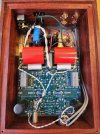
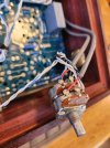
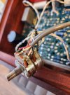
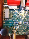
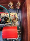
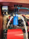
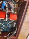
Here's some pictures of the board and a close up of the pot. I've attached the images but I can only upload low-res so here's a link to higher res pics:
Please let me know if there are any areas you want a closer look at and I'll take more
 

Attachments

  • 20240401_082221.jpg
    20240401_082221.jpg
    174.2 KB · Views: 13
  • 20240401_082556.jpg
    20240401_082556.jpg
    105.6 KB · Views: 16
  • 20240401_082553.jpg
    20240401_082553.jpg
    99.7 KB · Views: 12
  • 20240401_082243.jpg
    20240401_082243.jpg
    147.5 KB · Views: 10
  • 20240401_082239.jpg
    20240401_082239.jpg
    164.1 KB · Views: 9
  • 20240401_082232.jpg
    20240401_082232.jpg
    117.2 KB · Views: 10
  • 20240401_082228.jpg
    20240401_082228.jpg
    115.6 KB · Views: 14
It looks like one of his Aikido preamp boards? Unless I'm missing something when I ooked at the site. I see the builder added RCA output jacks, but didn't connect them and shorted them with those resistors. The only headphone amps I saw on his site had two tubes.
The rest were preamp boards and power supplies. Where is the headphone jack located? It's nice clean build though.
 
One possibility is that the shell of the pot isn't grounded to anything. Building Aikidos in wooden cases can be challenging, ask me how I know. ;-) You might try a tabbed washer on the pot with a wire to the board ground.
 
Is the body of the pot grounded? Kinda looks like it is, but just want to be sure. It should be, and grounding it to the input ground should be fine.

If its tied to the shield but doesn't actually have a connection to ground, thats probably why.
 
It looks like one of his Aikido preamp boards? Unless I'm missing something when I ooked at the site. I see the builder added RCA output jacks, but didn't connect them and shorted them with those resistors. The only headphone amps I saw on his site had two tubes.
The rest were preamp boards and power supplies. Where is the headphone jack located? It's nice clean build though.
Looks like it but was modified to be used exclusively as a headphone amp. You're right he shorted the second set of RCA jacks so probably was built originally with the plan to later convert it to have preamp capabilities. I've added a photo of where the 1/4" headphone jack is located. This one has an 0D3 power tube, 2 6H6pi and 2 6N1P preamp tubes
 

Attachments

  • amp image 2.png
    amp image 2.png
    221.1 KB · Views: 5
It does look like there is a blob of solder on the backside of the VC.
It looks like the cable shields are soldered to the backside, but I don't see where the shield is soldered to ground on the other end.
I wonder what mods were made? It looks like the headphone jack is connected where the output should be. I don't see anything that looks modified?
Anyone know how this would be made to work with headphones?
Changing the output impeadance maybe?
 
One possibility is that the shell of the pot isn't grounded to anything. Building Aikidos in wooden cases can be challenging, ask me how I know. ;-) You might try a tabbed washer on the pot with a wire to the board ground.
Is the body of the pot grounded? Kinda looks like it is, but just want to be sure. It should be, and grounding it to the input ground should be fine.

If its tied to the shield but doesn't actually have a connection to ground, thats probably why.
It does look like there is a blob of solder on the backside of the VC.
It looks like the cable shields are soldered to the backside, but I don't see where the shield is soldered to ground on the other end.
I wonder what mods were made? It looks like the headphone jack is connected where the output should be. I don't see anything that looks modified?
Anyone know how this would be made to work with headphones?
Changing the output impeadance maybe?


Imgur is being weird so I'll update this when it lets me grab a link again, but in the meantime here's some more pics

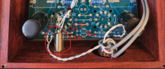
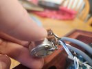
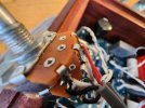
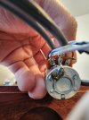
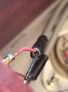
Couple of thoughts: It looks like the pot body has unshielded twisted metal cables that run to the inputs but doesn't actually connect to anything and ends right before the end of the shielding (last pic tucked between the red and black cables). I'm guessing it's not grounded then but I'm not sure what the purpose of these metal twisted cables are (again complete novice here). Could also try resoldering the solder on the back of the pot doesn't look the best (reference pic 4)


Also, in reference pic 3 that metal twisted cable slightly touches another part of the pot, could that be causing this?

Appreciate everyone's help with this!
 

Attachments

  • 20240401_103535.jpg
    20240401_103535.jpg
    63 KB · Views: 10
  • 20240401_103614.jpg
    20240401_103614.jpg
    127.1 KB · Views: 10
  • 20240401_104237.jpg
    20240401_104237.jpg
    95.3 KB · Views: 10
  • 20240401_104256.jpg
    20240401_104256.jpg
    88.8 KB · Views: 10
  • 20240401_104351.jpg
    20240401_104351.jpg
    85.4 KB · Views: 11
The backside of the pot looks like its grounded to the input grounds on the pots themselves.
Some feel grounding one end of rhe shields only helps reduce any noise that could be picked up. I've read arguments on whether one end or both should be grounded. I'm not sure grounding the pot to the input grounds is the best way to do it though? I never have. I've always used a grounding ring and grounded the VC to the main board ground or to the chassis where the board ground connects if mounting the volume control to wood.
 
The backside of the pot looks like its grounded to the input grounds on the pots themselves.
Some feel grounding one end of rhe shields only helps reduce any noise that could be picked up. I've read arguments on whether one end or both should be grounded. I'm not sure grounding the pot to the input grounds is the best way to do it though? I never have. I've always used a grounding ring and grounded the VC to the main board ground or to the chassis where the board ground connects if mounting the volume control to wood.

Definitely learning a lot from this post. So it looks like pot body is grounded to the input ground on the pot itself, which the input grounds to the PCB. The shield cables are also ground and connected to the pot body through the same connection. I believe this is properly grounded, but does it make sense to also run another ground cable from the pot body to the PCB ground just to be safe? I'm still not sure what could be causing that buzzing switching channels but I think it's narrowed down to the potentiometer
 
yeah the pot is grounded to the black wire in the pair, the sheild also ties in. The shield only being connected at one end is fine, the black is connected at both ends and there isn't any need for two paths to the same ground. Often you'll see only one end of a shielded or twisted pair connected to prevent ground loops.
 
Hopefully someone will chime in with how this was modified to be able to use as a headphone amp. Did you buy it from the person that built it?
If so could you ask them what mods they made?
Have you contacted the seller about the issue your having with it?
 
looks like I was posting about the same time as Lavane.

anyway, if the pot body measures low ohms to ground I think we're good. An un-grounded pot body is a common source of hum. Is the top plate tied to ground somewhere?
 
There should be a ground wire coming from the PCB to the chassis ground that's connected to the earth ground of the power socket. It looks like it is?
A black wire coming from the PCB connected to the green ground wire coming from the earth ground on the power socket. Both should be grounded to the chassis.
 
Back
Top Bottom