• The move to the new server is done. There are some software and database maintenance updates in process. This has us passing the hat around to help out. We appreciate any donations. Seriously, even a dollar helps. The payment page may be found here - https://www.audiokarma.org/support.html

Tube Amp Mystery Failure

Solheim

New Member
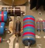
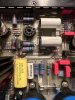
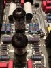
I have an Audio Research VT 130 that is presenting odd symptoms. It has blown a small resistor (see pic) twice- once dramatically. Sometimes you can hear buzzing in the left channel. Here's the odd thing- The V5 and V7 tubes glow brighter and dimmer at random times. (the rest of the tubes are steady) as if you were turning up and down a dimmer switch.

V5 and V 7 are both Sovtek 6550 tubes.

I'm guessing this is caused by voltage surge- from the power transformer perhaps?

I'd appreciate any ideas on a DIY repair. I have mad soldering skillz.
 

Attachments

Last edited:
Register to hide this ad
do you know which resistor that is?

what glows brighter, the heater or something inside the plate structure?

I don't actually see any tubes in the power supply of this thing. Just mosfets for voltage regulation. Is this the right schematic for your version of the amp ? I know ARC did sometimes use big power tubes in the supply for HV regulation but I don't see it on this schematic. Pics also don't look like it has any extra 6550 tubes, just the push-pull-parallel output set. This does run 4 output tubes per channel.
 
do you know which resistor that is?

what glows brighter, the heater or something inside the plate structure?

I don't actually see any tubes in the power supply of this thing. Just mosfets for voltage regulation. Is this the right schematic for your version of the amp ? I know ARC did sometimes use big power tubes in the supply for HV regulation but I don't see it on this schematic. Pics also don't look like it has any extra 6550 tubes, just the push-pull-parallel output set. This does run 4 output tubes per channel.
I made a few mistakes in my post- I have edited it.

I You are correct- there are no tubes in the power supply. I had that wrong. V5 and V7 were the ones with the variable brightness. No other tubes changed intensity. (I gotta say it was cool to see while it was happening)

Assuming I'm seeing/representing this correctly what was glowing was a vertical thread sized element in the center of the 6550 tubes.

Resistor ., 5.11Kù Mk-4 1% 50Ppm 15 per ARC's invoice. It failed with a bright flash of light and a puff of smoke- quite the show. We had the smelly electrical fire smell in the air for a while too.

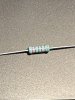
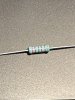
Here's a shot of the ARC replacement part. I have not installed it yet because I need to learn why it blew.
 

Attachments

  • Resistor.jpg
    Resistor.jpg
    114.5 KB · Views: 19
Last edited:
I made a few mistakes in my post and now can't edit it :(

I You are correct- there are no tubes in the power supply. I had that wrong. V5 and V7 were the ones with the variable brightness. No other tubes changed intensity. (I gotta say it was cool to see while it was happening)

Assuming I'm seeing/representing this correctly what was glowing was a vertical thread sized element in the center of the 6550 tubes.

Resistor ., 5.11Kù Mk-4 1% 50Ppm 15 per ARC's invoice. It failed with a bright flash of light and a puff of smoke- quite the show. We had the smelly electrical fire smell in the air for a while too.

Here's a shot of the ARC replacement part. I have not installed it yet because I need to learn why it blew.
Updated
 
Resistor ., 5.11Kù Mk-4 1% 50Ppm 15 per ARC's invoice.

I don't see any resistors of that value in the schematics you posted. The closest is R67 in the power supply, but that's 4.99K. You might need to determine its electrical location by tracing out the components it's connected to. Alternately, maybe call the factory and ask about this.

Jack
 
Not seeing a 5.11k on the schematic either. Do you know which resistor number it is ?

the tube heaters on all the outputs are run from the same source, so I suspect thats not what you were seeing. If you had arcing going on in the tube that will produce flashes. Thats usually a sign of a junk tube.
 
I don't see any resistors of that value in the schematics you posted. The closest is R67 in the power supply, but that's 4.99K. You might need to determine its electrical location by tracing out the components it's connected to. Alternately, maybe call the factory and ask about this.

Jack
Hi Jack;

The resistor pictured is the one that blew- and was supplied by ARC as the replacement for the OEM equipment resistor that first failed. It appears to be R15 connected to Valve 2. Left channel.

The lighting is poor but you can see that the printed circuit path includes an identical resistor and loops around at the edge and down to v2.
Resistor.jpg R14.jpg Resistor.jpg R14.jpg Resistor.jpg R14.jpg R14.jpg
 
Last edited:
Not seeing a 5.11k on the schematic either. Do you know which resistor number it is ?

the tube heaters on all the outputs are run from the same source, so I suspect thats not what you were seeing. If you had arcing going on in the tube that will produce flashes. Thats usually a sign of a junk tube.
Hi Gadget;

I'm pretty sure it wasn't arcing- just glowing brighter then softer about an hour before the resistor blew. I tried another tube in the socket and it was brighter than the rest as well. I'm stumped.

One other thing- there was distortion coming from the L speaker when this was occurring- and it was occasional- only a couple of times.
 
Sounds like possible red-plating on the tube. That lower of the two parallel large white capacitors also looks like it might have been stressed.
 
Sounds like possible red-plating on the tube. That lower of the two parallel large white capacitors also looks like it might have been stressed.

May well have been red plating- but why only these 2 tubes? And why that one resistor going out twice? I wonder it they are related or not?

All the components around that blown resistor got a good dose of carbon from the fire- it was an intense blow up. I saw it.
 
Not seeing a 5.11k on the schematic either. Do you know which resistor number it is ?

the tube heaters on all the outputs are run from the same source, so I suspect thats not what you were seeing. If you had arcing going on in the tube that will produce flashes. Thats usually a sign of a junk tube.
Hi Gadget;

Do you think it may possibly be a bias adjustment?
 
May well have been red plating- but why only these 2 tubes? And why that one resistor going out twice? I wonder it they are related or not?

All the components around that blown resistor got a good dose of carbon from the fire- it was an intense blow up. I saw it.
V5 and V7 work in parallel and are one side of the push pull output on the Left channel. The resister going out twice quite is possibly related and you are correct not to replace it until the cause is resolved. V5 and V7 should be tested as well a V2 and V3. However, until the actual circuit designation of this resistor is known everything is speculation. Can we see a picture of the Right channel board at the same location?
 
V5 and V7 work in parallel and are one side of the push pull output on the Left channel. The resister going out twice quite is possibly related and you are correct not to replace it until the cause is resolved. V5 and V7 should be tested as well a V2 and V3. However, until the actual circuit designation of this resistor is known everything is speculation. Can we see a picture of the Right channel board at the same location?

Here's the Right Channel- exact same layout but the valves are 11 and 12 not 1 and 2.
R channel.jpg
 
Sol -- If I may, the replacement resistor is indeed the correct replacement resistor, but I think because of the way the resistor is failing (in spectacular ways), its failure is likely not due to the actual circuit it serves.

That resistor is one of two resistors that make up the total of R13 on the amplifier schematic -- R13A and R13B -- both 5.1K resistors, which are connected in series to form the 10.22K resistor shown as R13A+B. The particular resistor that has failed is the resistor that is on the ground end of the total R13 resistor.

But notice, its mate -- the other 5.1K resistor it is connected in series with -- is located in a complementary way near the edge of the board, and it is perfectly fine. But the resistor in question has failed twice now. Therefore, it is quite unlikely that there is a fault in the R13 circuit (the cathode resistor for the pre-driver, which is the stage immediately preceding the cathode follower driver stage for the output stage. If there were a fault in that circuit, then the R13 mate would also show some level of distress as well, which it does not.

More likely then, it is quite possible that the fault is actually due to the layout of the physical board itself. That is, look at the two large resistors that are mounted perpendicular to the resistor in question -- those are two 100K resistors connected in parallel to form the 50K plate resistor R17A/B for the "bottom" pre-driver stage. The two complementary 100K resistors nearer the edge of the board form the 50K plate resistor R16A/B for the "top" pre-driver stage. However!.......

Note that the 320 vdc source that supplies R17A/B runs directly under the resistor that has failed -- but this is not the case for the supply trace that supplies R16A/B. The 320 vdc trace supplying those resistors takes a physically different path than directly under the R13 mate resistor. Therefore:

The section of R13A+B that has NOT failed (1) Operates at a higher potential above ground, since that portion of the total R13 resistor is connected to the cathode of the predriver, NOT ground, and (2), Does NOT have a 320 vdc trace running directly under it. In fact, the trace running under it operates at only about 57 vdc.

But the section of R13 that HAS failed operates at a lower potential relative to ground, since one end of it is in fact grounded, and (2) DOES have a 320 volt trace running directly under it. Therefore, the difference in potential between the traces running under the two R13 resistors, and the R13 resistors themselves, is very different. I strongly suspect that this -- based on the way that resistor is failing -- is the real root of the problem.

Therefore, I suggest that the failed resistor be removed, and the board and components under, near, and around it be carefully cleaned, so that no carbon traces remain from the previous blow up event(s). Dirt itself can contribute to arc over problems under the right circumstances. So bottom line, get the area where that portion of R13 resides good and clean. Check the bottom of the board in that area as well. Then, when you installed the new resistor, mount it notably ABOVE the board itself so that the body of the new resistor and the 320 vdc trace below it are not in close proximity. I think there is a very good chance that this will resolve your issue.

I hope this helps!

Dave

PS -- As to your glowing output tubes, it sounds very much like the screen grids are glowing. Therefore, I would check that the complete connections between pin 3 of the two output tube sockets in question, and where they connected to their respective OPT primary lead are all good, with no heat stress cracks that might cause the plate connections to partially disconnect from their OPT lead. If that happens, then the screen grids would have to carry all (or much more) of the total quiescent current in each tube, which would cause those grids to light up for sure!

 
Last edited:
Tall R.jpg
Sol -- If I may, the replacement resistor is indeed the correct replacement resistor, but I think because of the way the resistor is failing (in spectacular ways), its failure is likely not due to the actual circuit it serves.

That resistor is one of two resistors that make up the total of R13 on the amplifier schematic -- R13A and R13B -- both 5.1K resistors, which are connected in series to form the 10.22K resistor shown as R13A+B. The particular resistor that has failed is the resistor that is on the ground end of the total R13 resistor.

But notice, its mate -- the other 5.1K resistor it is connected in series with -- is located in a complementary way near the edge of the board, and it is perfectly fine. But the resistor in question has failed twice now. Therefore, it is quite unlikely that there is a fault in the R13 circuit (the cathode resistor for the pre-driver, which is the stage immediately preceding the cathode follower driver stage for the output stage. If there were a fault in that circuit, then the R13 mate would also show some level of distress as well, which it does not.

More likely then, it is quite possible that the fault is actually due to the layout of the physical board itself. That is, look at the two large resistors that are mounted perpendicular to the resistor in question -- those are two 100K resistors connected in parallel to form the 50K plate resistor R17A/B for the "bottom" pre-driver stage. The two complementary 100K resistors nearer the edge of the board form the 50K plate resistor R16A/B for the "top" pre-driver stage. However!.......

Note that the 320 vdc source that supplies R17A/B runs directly under the resistor that has failed -- but this is not the case for the supply trace that supplies R16A/B. The 320 vdc trace supplying those resistors takes a physically different path than directly under the R13 mate resistor. Therefore:

The section of R13A+B that has NOT failed (1) Operates at a higher potential above ground, since that portion of the total R13 resistor is connected to the cathode of the predriver, NOT ground, and (2), Does NOT have a 320 vdc trace running directly under it. In fact, the trace running under it operates at only about 57 vdc.

But the section of R13 that HAS failed operates at a lower potential relative to ground, since one end of it is in fact grounded, and (2) DOES have a 320 volt trace running directly under it. Therefore, the difference in potential between the traces running under the two R13 resistors, and the R13 resistors themselves, is very different. I strongly suspect that this -- based on the way that resistor is failing -- is the real root of the problem.

Therefore, I suggest that the failed resistor be removed, and the board and components under, near, and around it be carefully cleaned, so that no carbon traces remain from the previous blow up event(s). Dirt itself can contribute to arc over problems under the right circumstances. So bottom line, get the area where that portion of R13 resides good and clean. Check the bottom of the board in that area as well. Then, when you installed the new resistor, mount it notably ABOVE the board itself so that the body of the new resistor and the 320 vdc trace below it are not in close proximity. I think there is a very good chance that this will resolve your issue.

I hope this helps!

Dave

PS -- As to your glowing output tubes, it sounds very much like the screen grids are glowing. Therefore, I would check that the complete connections between pin 3 of the two output tube sockets in question, and where they connected to their respective OPT primary lead are all good, with no heat stress cracks that might cause the plate connections to partially disconnect from their OPT lead. If that happens, then the screen grids would have to carry all (or much more) of the total quiescent current in each tube, which would cause those grids to light up for sure!


Hi Dave;

Thanks for the informative post. I have installed the new resistor "way up high".

by accident I met a former Audio Research employee (he had some amps for sale) and we got to talking about this odd problem. He said "I know exactly what happened and how to fix it!"

It turns out that valve 5 and 7 are bad, and ARC uses resistors and not fuses to break faulty circuits. The reason he gave is that fuses affect sonic quality and ARC uses much slower a and larger fuses that don't always protect the circuits. In my case the slo-blo fuse frayed but didn't blow. The resistor did.

I ordered 2 new Sovtek 6550s from UpscaleAudio.com $173.73 shipped. I'm going to plug these in before trying to run the amp again.

I also used a surgical pick to tighten the female sockets just in case they had gotten loose. Careful inspection above and below the motherboard revealed no broken or loose connectors.

A thorough cleaning of the components and board was performed, and a part by part inspection and wiggling to expose bad solders, etc. No problem found.

My new valves should be here Tuesday so we shall see....I'll post my findings.

Again thanks for the help to you all!
 
doesn't this require matched quads per side ?

if this is indeed half of R13, I don't see how a V5/V7 failure could be related. Not saying they aren't bad, but gut feeling is the two problems are more coincidence than anything.
 
doesn't this require matched quads per side ?

if this is indeed half of R13, I don't see how a V5/V7 failure could be related. Not saying they aren't bad, but gut feeling is the two problems are more coincidence than anything.

It's R15. I have no idea why or how V5 & V7 relate to R15.

I was told that matching all tubes wasn't "all that important" which I think is ARC sacrilege. For now I'll pop in the fresh ones and carefully watch what happens. Meanwhile ARC has me on the wait list for a refurb- 4 weeks before I can send it in. It probably has lots of problems and lots of $ to be blown before it's right- and then it will still be a VT-130. See how I'm justifying a set of Ref 250s :)
 
Back
Top Bottom