Switching gears for a bit, I thought I would shed some light on the effects of changing tube types in these chassis. But first, some light on the differences and why they exist.
The Fisher three tube MPX sub-chassis exists in a veritable plethora of various model numbers, but all are a variation of the same theme: An input tube (V100) -- a 12AT7 or 12AX7 -- buffers and provides a small amount of amplification for the composite signal in the first section, to overcome losses later on in the circuit. It also separates the 19 kHz pilot signal from the composite signal, and then further amplifies the pilot signal in the second section. A second (always) 12AX7 (V101) then serves as a trigger stage in the first section, to synchronize the phase of the second section -- a 38 kHz oscillator -- with the phase of the pilot signal. Finally, a third tube (V102) -- a 12AT7 or 12AX7 -- then serves as a matrix amplifier in both sections, to equalize the level of the main L+R channel with that of the detected L-R sub-carrier channel. When that happens, optimum cancellation exists for maximum stereo channel separation at the output of the adapter. In all cases, either a 12AT7 was used for V100 AND V102, or a 12AX7 was used for both of these locations. There was never a combination of tubes and V100/102 locations. With either tube lineup, the adapter basically operates at unity gain, and does not change absolute phase.
With one significant exception, the circuit itself is basically identical between all the various models of this sub-chassis, with the biggest (most noticeable) difference between them being the tubes used. There were some minor changes in the matrix section -- the most significant of which relates to a resistor value in the de-emphasis circuits. But again, the obvious difference is with the tubes used. With the circuits being so similar across all model lines then, this of course has lead to all manner of tube type substitution experiments, and the resulting opinions as to which tubes sound or perform the best, and in what location. I have aligned a bunch of these in a stand alone setting lately, and decided to conduct some basic tests while I was at it to determine the effects produced by swapping tubes around in these chassis. More specifically, I targeted the effects of using a 12AT7 tube in chassis designating 12AX7 tubes for V100 and V102. But first, why the heck were they changed in the first place?
Truth be told, I don't think the reason had anything to do with the MPX design per say, but rather, it was all about Fisher trying to keep a handle on the amount of inventory items they had to carry. In this case, they're sights were set on eliminating the 12AT7 tube from their inventory. This tube has a long history with Fisher, being very common in many pieces of early Fisher gear, starting with the phono preamp of the 24B, and populating the 80AZ and 100 amplifiers, 400C preamp, 202T tuner/preamp, X202 integrated, FM-100B/200B tuners, and the 400-CX preamp to name just a few. But then, it suddenly vanished from Fisher designs. Why? Say hello to the 7247, a new low noise tube of the day (which the 12AT7 struggled to be) representing 1/2 of a 12AU7 and 1/2 of a 12AX7. It was perfect for high gain applications in one section, and high current applications in the other, so it was in, meaning something else -- the 12AT7 in this case -- had to go. Therefore, to my knowledge, after about 1961, NOTHING with the Fisher name on it was designed using a 12AT7. Going forward from that time then, the 400 CX-2, X-202B, and even the 300 FM Stereo Generator all used the 7247, with not a 12AT7 to be found anywhere. As a result, the backbone of the Fisher FM stereo MPX receiver program (the 400, 500C, and 800C) all had to have their multiplex sub-chassis operate with something other than the 12AT7's those chassis were originally designed to operate with. So what did they do to accomplish that? Actually, very little.
The tube used in the V100 position ideally needs two qualities about it:
1. Good gain to adequately amplify the composite and pilot signals, and
2. Adequate current capability to enable linear operation at a reasonably low impedance. This helps ensure that the integrity of the composite signal is maintained when amplified.
Those needs made the 12AT7 an excellent choice for this position, having both good gain and excellent current handling capability in both sections. At the V102 position, the same basic qualities are required to minimize gain loss, and maintain integrity between the main and detected sub-channels across the audio spectrum. So right off the drawing board, the 12AT7 becomes the tube of choice for both of these positions.
Against that however, the 12AX7 proved in fact to be a good second place finisher, certainly having the necessary gain, but also providing enough current handling capacity to work in the (basically) low impedance environment of the decoder circuit. However, the extra gain it displays over a 12AT7 provided an extra bonus, which leads to the one significant difference between 12AT7 and 12AX7 designated adapters.
The basic design of these adapters allows for an indicator of some type to be connected to it for the purposes of indicating reception of a stereo station. This is the signal that is available at lead #6 of the adapter when a stereo station is being received. This signal is a negative DC voltage produced from the peak value of the amplified pilot signal that is applied to the trigger section of V101, which of course would only be available during a stereo broadcast. But while the 12AT7 could easily amplify the pilot signal to a level required for dependable operation of the trigger stage, it didn't provide quite enough gain to produce enough negative DC voltage at the indicator output to properly operate the relay or eye tubes used to ultimately indicate FM Stereo broadcasts. As a result, the 12AT7 based decoders have an extra diode (CR101) included where the indicator output taps into the adapter circuit. This diode and C212 (as identified on the schematic of 12AT7 based decoders), forms a voltage doubler, doubling the normal DC output that is generated, to ensure that there will be enough voltage for the chosen indicator tube to work properly.
With the switch to a 12AX7 for V100 however, there is enough amplification of the pilot signal to not only produce dependable operation of the trigger stage, but also to produce enough negative DC voltage at the indicator output for the relay and eye tubes to do their jobs as well -- WITHOUT the need for the voltage doubling circuit installed in the 12AT7 based adapters. Therefore, the 12AX7 based adapters do not include CR101, and re-designated C212 to be a different component on 12AX7 based schematics. As a result, if a 12AT7 is installed at V100 in a 12AX7 based adapter, the stereo indicator will still work, but with somewhat reduced indicator sensitivity over that provided by a 12AX7. Basically, it might not provide a stereo indication for weaker stereo signals, where a 12AX7 otherwise would.
Also however, such a tube change alters the optimum setting required of the stereo separation control as well. This is due to differences between the HF response of the two tubes in the V100 position, relative to the spectrum making up the composite signal. The change is hardly so much as to ruin stereo separation, but is notable enough anyway.
So changing from a designated 12AX7 to a 12AT7 at V100 in 12AX7 adapters both reduces stereo indicator sensitivity, and reduces stereo separation as well.
At the V102 position, changing from a designated 12AX7 to a 12AT7 produces virtually no change in stereo separation performance at all, nor requires any change in the setting of the stereo separation control. From a theoretical standpoint however, a 12AT7 installed at the V102 position will provide greater headroom in driving the 38 kHz filters and de-emphasis networks that appear at the output of this stage.
There are other, minor differences between the various three tube chassis, but when they exist, they are largely confined to small changes adapting the indicator output to the particular unit the adapter is installed in.
A few pics are included:
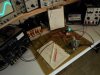
1. All set up and ready to go, with an adapter operating from the test jig.
2. The adapter connects to the test jig by short leads with test clips connected to the test jig.
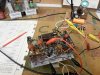
3. Troubleshooting is real easy with the unit operating in a stand alone fashion -- you can really get at the components rather easily. This particular adapter has some significant problems.......
4. A shot of the 38 kHz sub-carrier it was attempting to generate. This adapter produced beautiful FM........Mono....... out of both channels. No warbling or tricky tuning, just mono sound. That's due to a dead 38 kHz oscillator transformer, allowing no detection of the 38 kHz sub-carrier.
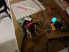
5. The test jig has an eye tube built into it, which is calibrated to allow a normal, properly aligned adapter to completely close the eye. It makes for a quick and easy visual check of proper indicator output. This is a shot of the eye tube with a 12AX7 based adapter with 12AX7s installed.
6. The same adapter with 12AT7s installed.
So there you have it. From a strict design standpoint, the original adapters with 12AT7 tubes designated for V100 and V102 are the best designs. However, the all 12AX7 adapters are hardly chopped liver, producing excellent overall performance and stereo decoding. You can use whichever tube you prefer in either location. But now at least you'll know what the effect is that such changes have on the operation of the adapter, and the unit it is installed in.
Dave
The Fisher three tube MPX sub-chassis exists in a veritable plethora of various model numbers, but all are a variation of the same theme: An input tube (V100) -- a 12AT7 or 12AX7 -- buffers and provides a small amount of amplification for the composite signal in the first section, to overcome losses later on in the circuit. It also separates the 19 kHz pilot signal from the composite signal, and then further amplifies the pilot signal in the second section. A second (always) 12AX7 (V101) then serves as a trigger stage in the first section, to synchronize the phase of the second section -- a 38 kHz oscillator -- with the phase of the pilot signal. Finally, a third tube (V102) -- a 12AT7 or 12AX7 -- then serves as a matrix amplifier in both sections, to equalize the level of the main L+R channel with that of the detected L-R sub-carrier channel. When that happens, optimum cancellation exists for maximum stereo channel separation at the output of the adapter. In all cases, either a 12AT7 was used for V100 AND V102, or a 12AX7 was used for both of these locations. There was never a combination of tubes and V100/102 locations. With either tube lineup, the adapter basically operates at unity gain, and does not change absolute phase.
With one significant exception, the circuit itself is basically identical between all the various models of this sub-chassis, with the biggest (most noticeable) difference between them being the tubes used. There were some minor changes in the matrix section -- the most significant of which relates to a resistor value in the de-emphasis circuits. But again, the obvious difference is with the tubes used. With the circuits being so similar across all model lines then, this of course has lead to all manner of tube type substitution experiments, and the resulting opinions as to which tubes sound or perform the best, and in what location. I have aligned a bunch of these in a stand alone setting lately, and decided to conduct some basic tests while I was at it to determine the effects produced by swapping tubes around in these chassis. More specifically, I targeted the effects of using a 12AT7 tube in chassis designating 12AX7 tubes for V100 and V102. But first, why the heck were they changed in the first place?
Truth be told, I don't think the reason had anything to do with the MPX design per say, but rather, it was all about Fisher trying to keep a handle on the amount of inventory items they had to carry. In this case, they're sights were set on eliminating the 12AT7 tube from their inventory. This tube has a long history with Fisher, being very common in many pieces of early Fisher gear, starting with the phono preamp of the 24B, and populating the 80AZ and 100 amplifiers, 400C preamp, 202T tuner/preamp, X202 integrated, FM-100B/200B tuners, and the 400-CX preamp to name just a few. But then, it suddenly vanished from Fisher designs. Why? Say hello to the 7247, a new low noise tube of the day (which the 12AT7 struggled to be) representing 1/2 of a 12AU7 and 1/2 of a 12AX7. It was perfect for high gain applications in one section, and high current applications in the other, so it was in, meaning something else -- the 12AT7 in this case -- had to go. Therefore, to my knowledge, after about 1961, NOTHING with the Fisher name on it was designed using a 12AT7. Going forward from that time then, the 400 CX-2, X-202B, and even the 300 FM Stereo Generator all used the 7247, with not a 12AT7 to be found anywhere. As a result, the backbone of the Fisher FM stereo MPX receiver program (the 400, 500C, and 800C) all had to have their multiplex sub-chassis operate with something other than the 12AT7's those chassis were originally designed to operate with. So what did they do to accomplish that? Actually, very little.
The tube used in the V100 position ideally needs two qualities about it:
1. Good gain to adequately amplify the composite and pilot signals, and
2. Adequate current capability to enable linear operation at a reasonably low impedance. This helps ensure that the integrity of the composite signal is maintained when amplified.
Those needs made the 12AT7 an excellent choice for this position, having both good gain and excellent current handling capability in both sections. At the V102 position, the same basic qualities are required to minimize gain loss, and maintain integrity between the main and detected sub-channels across the audio spectrum. So right off the drawing board, the 12AT7 becomes the tube of choice for both of these positions.
Against that however, the 12AX7 proved in fact to be a good second place finisher, certainly having the necessary gain, but also providing enough current handling capacity to work in the (basically) low impedance environment of the decoder circuit. However, the extra gain it displays over a 12AT7 provided an extra bonus, which leads to the one significant difference between 12AT7 and 12AX7 designated adapters.
The basic design of these adapters allows for an indicator of some type to be connected to it for the purposes of indicating reception of a stereo station. This is the signal that is available at lead #6 of the adapter when a stereo station is being received. This signal is a negative DC voltage produced from the peak value of the amplified pilot signal that is applied to the trigger section of V101, which of course would only be available during a stereo broadcast. But while the 12AT7 could easily amplify the pilot signal to a level required for dependable operation of the trigger stage, it didn't provide quite enough gain to produce enough negative DC voltage at the indicator output to properly operate the relay or eye tubes used to ultimately indicate FM Stereo broadcasts. As a result, the 12AT7 based decoders have an extra diode (CR101) included where the indicator output taps into the adapter circuit. This diode and C212 (as identified on the schematic of 12AT7 based decoders), forms a voltage doubler, doubling the normal DC output that is generated, to ensure that there will be enough voltage for the chosen indicator tube to work properly.
With the switch to a 12AX7 for V100 however, there is enough amplification of the pilot signal to not only produce dependable operation of the trigger stage, but also to produce enough negative DC voltage at the indicator output for the relay and eye tubes to do their jobs as well -- WITHOUT the need for the voltage doubling circuit installed in the 12AT7 based adapters. Therefore, the 12AX7 based adapters do not include CR101, and re-designated C212 to be a different component on 12AX7 based schematics. As a result, if a 12AT7 is installed at V100 in a 12AX7 based adapter, the stereo indicator will still work, but with somewhat reduced indicator sensitivity over that provided by a 12AX7. Basically, it might not provide a stereo indication for weaker stereo signals, where a 12AX7 otherwise would.
Also however, such a tube change alters the optimum setting required of the stereo separation control as well. This is due to differences between the HF response of the two tubes in the V100 position, relative to the spectrum making up the composite signal. The change is hardly so much as to ruin stereo separation, but is notable enough anyway.
So changing from a designated 12AX7 to a 12AT7 at V100 in 12AX7 adapters both reduces stereo indicator sensitivity, and reduces stereo separation as well.
At the V102 position, changing from a designated 12AX7 to a 12AT7 produces virtually no change in stereo separation performance at all, nor requires any change in the setting of the stereo separation control. From a theoretical standpoint however, a 12AT7 installed at the V102 position will provide greater headroom in driving the 38 kHz filters and de-emphasis networks that appear at the output of this stage.
There are other, minor differences between the various three tube chassis, but when they exist, they are largely confined to small changes adapting the indicator output to the particular unit the adapter is installed in.
A few pics are included:
1. All set up and ready to go, with an adapter operating from the test jig.
2. The adapter connects to the test jig by short leads with test clips connected to the test jig.
3. Troubleshooting is real easy with the unit operating in a stand alone fashion -- you can really get at the components rather easily. This particular adapter has some significant problems.......
4. A shot of the 38 kHz sub-carrier it was attempting to generate. This adapter produced beautiful FM........Mono....... out of both channels. No warbling or tricky tuning, just mono sound. That's due to a dead 38 kHz oscillator transformer, allowing no detection of the 38 kHz sub-carrier.
5. The test jig has an eye tube built into it, which is calibrated to allow a normal, properly aligned adapter to completely close the eye. It makes for a quick and easy visual check of proper indicator output. This is a shot of the eye tube with a 12AX7 based adapter with 12AX7s installed.
6. The same adapter with 12AT7s installed.
So there you have it. From a strict design standpoint, the original adapters with 12AT7 tubes designated for V100 and V102 are the best designs. However, the all 12AX7 adapters are hardly chopped liver, producing excellent overall performance and stereo decoding. You can use whichever tube you prefer in either location. But now at least you'll know what the effect is that such changes have on the operation of the adapter, and the unit it is installed in.
Dave