• The move to the new server is done. There are some software and database maintenance updates in process. This has us passing the hat around to help out. We appreciate any donations. Seriously, even a dollar helps. The payment page may be found here - https://www.audiokarma.org/support.html

Tuner dial spread

Racingh11

Super Member
I am working on an MCS 3230. Going through and adjusting the FM tuner section. It has the typical steps of setting the dial to a signal at the high end of the dial and adjusting a trimmer capacitor. Then tuning to a signal at the low end of the dial and adjusting a variable inductor. The problem is; when one is adjusted it pulls the band in on the other end. I can get all stations in very clearly, but the stations are not spread all the way across the dial. I can line up either end for accuracy, but it will be off by more than .5 Mhz at the other end of the dial. I tried modifying the trimmer cap for the oscillator with an RC circuit. It moved it to a different tuning spot on the trimmer cap, but no change to spread out the adjustment. If I do keep adjusting the coil and cap towards that direction, at some point it does not receive any stations. It only works properly when the spread is narrow. Anyone know what could cause a problem like this? The mechanical system and pulley all look as they should. I could possibly scan the schematic later and post it.
 
Last edited:
Register to hide this ad
I'm not familiar with the model, but I'm assuming that it uses an air-vaned tuning capacitor. Can you confirm that the tuning cap is moving all the way from having its vanes fully meshed to fully un-meshed? Are any vanes bent, or missing?
 
I'm not familiar with the model, but I'm assuming that it uses an air-vaned tuning capacitor. Can you confirm that the tuning cap is moving all the way from having its vanes fully meshed to fully un-meshed? Are any vanes bent, or missing?
Yes, air cap. And everything goes all the way. The coil and cap I mentioned in the post were both for the oscillator circuit. The thing is, it doesn't have to travel all the way to go through the whole FM broadcast range.
 
Anyone know what could cause a problem like this?

I typically see this when the LO isn't tracking properly. Usually one gang of the tank circuit is used for front end filtering; creating a resonant circuit to provide some band-pass filtering for the signal you want. Another gang in the tank circuit is used to tune the local oscillator. Most alignment procedures I've seen have you peak the tank circuit for each end of the band; and then you have to adjust the tank circuit so the LO tracks properly.

The service manual should have the proper alignment procedure. If you just have the schematic, it's possible you're missing the step of adjusting the LO tracking.
 
it doesn't have to travel all the way to go through the whole FM broadcast range.

Ah, right - as you may have gathered, I was thinking about this backwards. (I was thinking there was too little capacitance change as the cap rotates, when the symptom suggests too much change.) I guess it could still be bent vanes in the oscillator section of the tuning cap, causing the fully-meshed capacitance to be greater than it's supposed to be. But that seems like a long shot. Perhaps some sort of contamination on the vanes?

Other than these feeble speculations, I got nothin'.
 
I typically see this when the LO isn't tracking properly. Usually one gang of the tank circuit is used for front end filtering; creating a resonant circuit to provide some band-pass filtering for the signal you want. Another gang in the tank circuit is used to tune the local oscillator. Most alignment procedures I've seen have you peak the tank circuit for each end of the band; and then you have to adjust the tank circuit so the LO tracks properly.

The service manual should have the proper alignment procedure. If you just have the schematic, it's possible you're missing the step of adjusting the LO tracking.
I do have the service manual for it. My memory is somewhat fuzzy on it as I haven't worked on it in a few months. Was planning on getting back at it now and just wanted some ideas. I will double check what you mentioned, but it seems to me I played around with all the adjustments as much as I could and nothing seems to change it. It's also not the first one of these units I have tuned and don't remember any issues on the last one. Most receivers I work on don't have an adjustable oscillator coil, just the trimmer cap on top of the variable tuning capacitor. Just something I noticed about this one.
 
Ah, right - as you may have gathered, I was thinking about this backwards. (I was thinking there was too little capacitance change as the cap rotates, when the symptom suggests too much change.) I guess it could still be bent vanes in the oscillator section of the tuning cap, causing the fully-meshed capacitance to be greater than it's supposed to be. But that seems like a long shot. Perhaps some sort of contamination on the vanes?

Other than these feeble speculations, I got nothin'.
That would make sense. Although I don't think it is the case. I will take a closer look though.
 
Most receivers I work on don't have an adjustable oscillator coil, just the trimmer cap on top of the variable tuning capacitor.

So usually the variable tuning capacitor, at least one section of it, is part of the LO circuit. In a resonant LC (inductor/capacitor) circuit changing either the inductor or capacitance will affect the resonant frequency. So you can tune the circuit by changing the value of the inductor or the value of the capacitor. Since you're changing the value of the capacitor already, it's "easier" to change the capacitance to change the frequency of the LO. Plus you can help ensure your LO is operating at the proper range across the dial.

In most of the radios I do; you're modifying the coils to tune the IF circuits and you're trimming the tuning cap for the LO value.
 
So usually the variable tuning capacitor, at least one section of it, is part of the LO circuit. In a resonant LC (inductor/capacitor) circuit changing either the inductor or capacitance will affect the resonant frequency. So you can tune the circuit by changing the value of the inductor or the value of the capacitor. Since you're changing the value of the capacitor already, it's "easier" to change the capacitance to change the frequency of the LO. Plus you can help ensure your LO is operating at the proper range across the dial.

In most of the radios I do; you're modifying the coils to tune the IF circuits and you're trimming the tuning cap for the LO value.
Correct, but this unit will change the position of the dial from two adjustment points that are to be adjusted at each end of the dial per service manual instruction. That's why this unit is odd, the trimmer coil is an oscillator adjustment, not RF or IF. I don't have the manual here right now, but I will try to post some scans if I can later or tomorrow.
 
Cleaning the front end as described in the sticky at the top of the forum. Check physical pointer alignment. Sometime loosening the pointer and physically moving it tad one way or another can make it line up better.
 
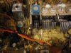
I finally got around to looking at this again. The cause of the alignment issue was the oscillator not tracking properly. The reason it had an issue was because a screw that attaches the front-end shielding to the vari-cap, was too long and was rubbing on the last fin of the oscillator. It had actually worn a groove in the fin and looks original. I backed the screw off and tweaked the plates around until everything lined up.IMG_4099.JPG
 
Is it possible that the two adjustments are iterative in nature? One affects the other, so you go around through the adjustment procedure a few times and eventually approach the correct setting for both adjustments. I am not familiar with this tuner.
 
Back
Top Bottom