• The move to the new server is done. There are some software and database maintenance updates in process. This has us passing the hat around to help out. We appreciate any donations. Seriously, even a dollar helps. The payment page may be found here - https://www.audiokarma.org/support.html

Turntable RCA Connector Replacement

Iamstubbb

AK Subscriber
Subscriber
Hi Folks, I am restoring a Techincs SL-D2 turntable that had been parted out and had a bad RCA connector. As a replacement for the RCA, I thought I might be able to use a spare RCA connector that is of decent quality. It is one of the connectors that that has a double end at the connector side, but the main run is a single cable. The ground/shield wires combine at the junction, and the main run is a three-conductor shielded cable that splits again at the other side. Will this work as a replacement?

I notice on phono preamp schematics I have that the ground is common once it enters the preamp (but different from the chassis ground), so I am thinking of jumping the common ground at the connector board in the turntable where the tonearm wires connect to the RCA out. Any reason not to do that? It would be a neater solution than the traditional independent conductor cables normally attached.
 
Register to hide this ad
There are two different grounds, one for signal and the chassis ground.

The signal ground is often one per channel from cartridge to preamp input, as it combines at the preamp input jacks. You don't need both though, you really only need 3 signal wires from the cart to the preamp, left and right can share. You do want to make sure that you don't have both signal grounds connected to each other at both ends. If they are combined at the cart, only have one signal ground going to preamp. You can convert some older mono tables to stereo this way. So yes, you can combine at the table itself, just don't make a loop by connecting both at both ends.


Star grounding vs plane grounding. The concept is a bit ancillary to this, but an interesting read and very beneficial to those of us tinkering. Worth wrapping the head around.
 
Thanks for the response! The AK server upgrade seems to have messed up my ability to include photos. Here is the internal connector if you can see it:
Technics RCA output Connection
My understanding of cartridge wiring is limited, but it seems that the - coil leads in either MM or MC are ultimately connected to ground at the preamp stage, but I am not sure they are equivalent leaving the cartridge to the RCA connector so it would seem in a three-lead conductor setup you would want the third lead connected to both - coil outputs, meaning jumping the - at the connector. Luckily they are labelled on the connection board, so I won't accidently create a mono turntable!
I did learn about ground schemes for amps the hard way when I thought I messed up a voltage regulator only to later learn (thanks Grok) that power stage and regulator stages were separated from the chassis in some designs so I had the wrong reference and could never see the correct voltage. That's why this is a hobby and not something I'd try to make a living off of.
 
The signal ground is often one
Technically, there is no signal ground coming from a cartridge. All MM/MC/MI cartridges are floating by design.
Most MM/MI cartridges have a tab on the rear that connects one of the cold pins (the green one) to the mu metal shield. This is with some cartridges connected to ground by their design (stanton, pickering etc).
This tab is removable for a very important reason and that is the same reason that you don't want any of your signal wires coming out of the turntable connected to ground within the turntable.
Some of the preamps have a balanced setup. Balanced setup uses floating hot and cold referenced to an external ground. The idea behind that is that outside interference will have the same influence on hot and cold and will therefore give no net result. But there has to be an external ground to do that.
If one of the signal wires is connected to a machine ground inside the turntable, a balanced preamp can't function in balanced mode anymore. This also goes partly when both cold sides of the cartridge channels are connected together as interference can come into one channel and it will automatically be transferred to the other channel, but only on 1 conductor.
So whether or not the ground should be connected to the cold side of the signal wires (or whether or not both cold sides should be connected) should be determined in the phono preamp, not in the turntable or cable.
 
I wish I could get a photo added here. There is a separate ground plane/machine connection on the cartridge/RCA interface PCB that has a mechanical connection to the tonearm hardware and serves as the separate ground lead for the external phono ground connection. This is clearly independent so there is no concern that the cartridge leads will connect. I think the main issue is that if the cold (blue/green) cartridge leads are not equivalent until they are ultimately unified in the phono preamp, then with a three-conductor signal cable, the third conductor should carry a unified blue AND green status and be appropriate. The signals are just summed earlier in the chain. If the third conductor carried only the blue OR green connector's potential, then one of the hot signals would refer to an incorrect reference, such as red and white referring to green or blue only, rather than both referring to the summed blue+green.

Who knew this would be this hard? I think I'll just go to best buy and get a dual lead cable!
 
(...) I think I'll just go to best buy and get a dual lead cable!

Maybe. However, you should make sure to get a cable with not only reasonably good shielding, but also known cable capacitance - at least, if you intend to use a typical MM or MI cartridge. Because ideally you want a cable with reasonably low capacitance, so that the sum of the cabling capacitance of the turntable/tonearm (*) and the input capacitance of the phono stage is within the manufacturer-suggested load capacitance range for the cartridge model, which you intend to use. Hence buying a randon RCA interconnect cable with unknown capacitance is not really a good idea.

Greetings from Munich!

Manfred / lini

*) For the cabling inside the turntable/tonearm you can typically expect a capacitance of ~ 30 to 50 pF.
 
Hello Munich!
I suppose I should measure it and compare the original, but I've since tossed the old cable. A 5.5ft/1.7m run of the proposed cable reads 147pF between outer and inner conductor on decent handheld oscilloscope/multimeter and 200pF on my cheap one. That should fall within the 200pF +/- range. The stock length was 3.5 ft/1m. Perhaps I'll shorten the cable and measure the effect. My amps/preamps have either no setting/ MM, or settings at 100/200/300 pF and MM/MC selectors so I guess that would be fine. I compared with a 4ft/1.2m run of R59 coax and that was zero. Maybe I should use that if I can fit it to the turntable!
 
Well, that ended up not being much of solution.:( What seems to be needed is a cable with a drain wire on the shielding. Coax is probably the solution, humorous as it seems, but it is too fat. The shielded cable was a partial solution. With the connected ground between channels there was a low hum. With independent grounds it was worse. I rigged a drain connection by inserting a piece of connector I cut from a capacitor I was replacing, and the hum went down by orders of magnitude but didn't disappear. I swapped out the RCA cable from another turntable, and it was silent. That connector was a single conductor/shield+drain configuration, not a shielded 2C. So I ordered some 22awg single conductor signal wire with a drain and see how that goes. I also found a stock RCA connection and other bonus bits from a parted-out TT on ebay from the same model (Technics SL-D2) for $10. I'll compare those. Lesson learned. Here is the internal connector pcb with marking where I jumped the ground. This little experiment showed me why my DIY equipment interconnects made with R59 coax work so well. Thanks for the input!
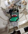
20260724_234705-marked.jpg
 
Indeed, coax style wire is very commonly used for phono.

Microphone cables can also work well.
 
Coax is probably the solution, humorous as it seems, but it is too fat.
Sorry, I hope this wasn't in reference to my emoji. I was laughing at the "Hello Munich!" response, since the AKer you responded to goes by the name Manfred (who is from Munich). His name is below the "Greetings from Munich!" statement.
 
Well, that ended up not being much of solution.:( What seems to be needed is a cable with a drain wire on the shielding. Coax is probably the solution, humorous as it seems, but it is too fat.
All you need is simple coax cable (ie one central conductor plus shield). Connect the central conductor to + and the shield to -. Obviously, one run of cable per channel. The black wire in the picture above is what is usually called the "ground wire", though that's a bit of a misnomer - it doesn't have to connect to mains ground. The black wire is a separate wire which should run alongside the other two lengths of cable and connect the ground post on the amplifier or phonostage.

I see lots of posts here on the forum where people over-complicate things with "two core plus shield" microphone cable and get confused (and receive confusing advice) about how to connect everything up.
 
All you need is simple coax cable (ie one central conductor plus shield). Connect the central conductor to + and the shield to -. Obviously, one run of cable per channel. The black wire in the picture above is what is usually called the "ground wire", though that's a bit of a misnomer - it doesn't have to connect to mains ground. The black wire is a separate wire which should run alongside the other two lengths of cable and connect the ground post on the amplifier or phonostage.

I see lots of posts here on the forum where people over-complicate things with "two core plus shield" microphone cable and get confused (and receive confusing advice) about how to connect everything up.
Yes, I shouldn't be ambiguous about "ground". I think that is a discussion for grounding schemes used in different amps. Not understanding that caused me a bunch of trouble when working out a bad voltage regulator section of an amp I was working on.

I would love to use coax, as I have a bunch of it laying around and I've used it for interconnects for other things. The problem here is access. If you look at the bottom where the "ground" is, there is limited space and I can't get two runs of R59 through it. I got some 22-gauge shielded single conductor wire with a drain, but the diameter is so thin it may be impractical when connected to an RCA. I do think Belden 8451 22 AWG 2C mic line might be the solution for that reason and because it has a known spec. Connecting 1 conductor plus the drain to negative would result in a 220pF capacitance for 1M (67pF/ft). I don't know what both conductors connected to positive and just the drain to negative would measure, but I could probably measure it reasonably well. I just need to find somewhere to buy less than 100ft! The OEM connector was a shielded single conductor connected to positive and a drain connected to negative.
 
Connecting 1 conductor plus the drain to negative would result in a 220pF capacitance for 1M (67pF/ft).
220pF for a 1 metre length of cable sounds rather high. "Low" capacitance would be about 60pF. Typical capacitance for pretty standard cable would be about 100pF - 120pF.
 
220pF for a 1 metre length of cable sounds rather high. "Low" capacitance would be about 60pF. Typical capacitance for pretty standard cable would be about 100pF - 120pF.
I thought so too, thanks for pointing that out. Found this supplier who makes blunt RCA cables but also sells the cable by the foot. I think this is the stuff. I already have RCA connectors, so I just ordered cable. Their specs show 21pF/ft or 69pF for a 1 meter run in the drain+negative/positive configuration. Right in the ballpark you suggested. And I like the jacketing. It looks like a good cable for interconnects.

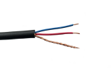
24 AWG 2 Conductor Shielded - CCCM242
 
I thought so too, thanks for pointing that out. Found this supplier who makes blunt RCA cables but also sells the cable by the foot. I think this is the stuff. I already have RCA connectors, so I just ordered cable. Their specs show 21pF/ft or 69pF for a 1 meter run in the drain+negative/positive configuration. Right in the ballpark you suggested. And I like the jacketing. It looks like a good cable for interconnects.

24 AWG 2 Conductor Shielded - CCCM242
That isn't a drain, it's a shield. A drain wire is what runs alongside aluminium foil shielding because you can't solder to aluminium.
And why do you need two conductors plus shield? Why not one conductor plus shield?
 
That isn't a drain, it's a shield. A drain wire is what runs alongside aluminium foil shielding because you can't solder to aluminium.
And why do you need two conductors plus shield? Why not one conductor plus shield?
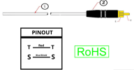
I apologize for not not being clear. To define terms, for me a drain is the bare conductor alongside the shielding that provides connectivity for grounding or otherwise compensating for interference, as you state. Above I mentioned that I got some 22AWG shielded single conductor with a drain, which matched what came off the original. The overall cable was too thin, 2.5mM, for practical use with an RCA connector. It would look silly. It was similar to signal wire used for laboratory equipment which would normally connect to something like a phoenix connector. What is needed here is a shielded single conductor with a drain. A foil or braided shield is not useful for connections, soldered or otherwise, which is why there is a drain wire. A straight-up two conductor connection does not work for this application, even if shielded. That was my failed experiment above. The shield drain should be connected to the negative on that board to normalize interference, and the conductor connected to the positive. But good luck finding that in a format suitable for use with an RCA connector. Below is the cable I ordered, which has a more robust outer cover and suitable for pairing with an RCA connector. The bare copper conductor is the drain running alongside the shield. How the manufacturer constructs a shielded RCA connector is below that. The last figure shows the XLR to RCA configuration. A balanced XLR to unbalanced RCA connector is configured by connecting the shield drain and negative together. It is true that in my application I could just connect the drain to the negative and one conductor to the positive, but it is in the configuration of drain+conductor/conductor that the manufacturer gives the 21 pF/ft spec, which is useful to know. I hope I am making sense! If not, how would you configure this? In your opinion, is about 70pF appropriate for a phono RCA connector? I think that would translate to a 100-200pF loading for the phono preamp.
1785919802646.png
1785920597278.png

1785918937767.png
 
(...) What is needed here is a shielded single conductor with a drain. (...)

A few comments:

The original Technics SFDH212-01 cable for the SL-D2 and quite a few other Technics models is a twin coax type, as usual.

An additional drain wire isn't necessary - together all the thin wires of the shield braid have a sufficiently low resistance.

The cable type depicted above quite obviously doesn't sport an additional drain wire. Or in other words: What you'd appear to deem to be a drain wire rather are the wires of the shield braid twisted together.

If you'd like a a decent twin cable type, that's similar to the original, you could for example consider Mogami W2947 (twin 3mm outer diameter) or W2965 (twin 4.8 mm outer diameter), depending on what would fit through the opening.

Greetings from Munich!

Manfred / lini
 
A few comments:

The original Technics SFDH212-01 cable for the SL-D2 and quite a few other Technics models is a twin coax type, as usual.

An additional drain wire isn't necessary - together all the thin wires of the shield braid have a sufficiently low resistance.

The cable type depicted above quite obviously doesn't sport an additional drain wire. Or in other words: What you'd appear to deem to be a drain wire rather are the wires of the shield braid twisted together.

If you'd like a a decent twin cable type, that's similar to the original, you could for example consider Mogami W2947 (twin 3mm outer diameter) or W2965 (twin 4.8 mm outer diameter), depending on what would fit through the opening.

Greetings from Munich!

Manfred / lini
Perfect! W2947 is just what I have been looking for. I think we've been getting caught up on semantics a bit. Thank you for that. Now to find someone who sells it.

When a braid is twisted into a wire for connection versus a metal foil shield with an accompanying bare wire for connection, should it be called a drain, a wire, or a twisted braid? The original cable I was working with had a metal foil shield and no bare wire or way to connect it. In my line of work, a twisted braid or a bare wire on a foil shield for connections are both called drains.

Anecdotally, this reminds me of being on a train with a person from Nijmegen and a person from Utrecht getting quite animated in accusing each other of mis-pronouncing their own town names!

Cheers! (Tchuss?)
 
Well, after all that I ended up finding an OEM replacement and returned the unit to stock condition. I couldn't get W2947 anywhere for a reasonable price. I did get the CCM242 mentioned in the earlier post. It is great cable with good specs and perfectly sized for RCA connectors. I highly recommend it. But the shielding was too thick to fit into the plinth without modifying in some way, which I am loathe to do. Instead I think I will be making interconnects with it. Much more flexible than R59 coax, which I have used with good results. The turntable itself is playing well under testing with an AT VM95ML cartridge installed. Another turntable saved from the scrap heap and ready for years of good service.

Now-to explore sound dampening on the plinth...

Thanks for the advice and opinions everybody. Very helpful and I learned a lot in the process.
 
Back
Top Bottom