• The move to the new server is done. There are some software and database maintenance updates in process. This has us passing the hat around to help out. We appreciate any donations. Seriously, even a dollar helps. The payment page may be found here - https://www.audiokarma.org/support.html

Two quick easy questions - resistor wattage and diode rectifier

loomis

bland
Hi. Old, cheap, Japanese guitar amp. I got it running and rebuilt the power supply caps but I need to rebuild this messy, broken turret board. Two questions:

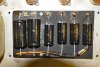
1) Photo 1. These grey wire-wound resistors. Safe to assume the short 20k one is 5w, and the long 20k one is 10w? They're not marked. Can I replace these with ceramic resistors, or do they have to be wire-wound?

2) Photo 2. This solid state rectifier thing. It's marked with an unknown symbol and "SM." Is this a diode? Can I replace this with (refresh my memory) a 1N4004? 1N4007? Which way does the stripe go again?

Thanks

resistors.jpg diode.jpg
 
Register to hide this ad
If the resistors check within tolerance, I would leave 'em be. Also, if that diode isn't giving you any problems, I would leave that one be also.
 
No can do, the legs are broken off the resistors, so I need to know the above questions. You can see the crap repair red wire on the one leg in the first picture on the left. Thanks.
 
Not to go through formulas...
You can use dropping resistor calculator from the web.
http://elecurls.tripod.com/drop-res.htm

Measure existing resistor. If amp can be turned on, after voltages stabilize, measure voltage drop across the resistor. Input start and output voltages into calculator. If you input correct load into calculator - it will show your measured resistance and minimum resistor wattage rating. I'd probably triple that to be safe.
Stripped end of diode is cathode
 
Or divide voltage drop by measured resistance. That will give you approximate amp load across resistor. Multiply that number by the voltage drop to get wattage. That would be your starting point at idle.
 
Dogbone resistors. Smaller one would be 5 watts and the two bigger one's would be 10 watt.

Agree to leave the diode alone.

It looks like you need some silver solder or a better iron.
 
Man, some funky tech work previously done to that unit. I'd clean-up and reposition those "sandbox" ones. The 470-ohm one next to the 50mfd 'lytic suspiciously look like cathode bias arrangement on a single-ended 6V6GT output stage. :D
 
Hello. Guys I didn't do the work that's visible in the photos. It's done poorly.

I cannot measure the resistors because two of their legs snapped off and are barely patched on, just enough so that I could pass signal on a variac, ensure it works, and then shut it down.

So I again just wanted to know if the dogbone wire-wounds need be replaced with same, or can I use ceramic ones? And also, the long ones should be 10w and the short 5w?

I need to rebuild the entire turret board. What's the reason for having to keep that old diode?

It's a 6AQ5 amp, and I assumed that diode was the rectifier?
 
Last edited:
Just replace them with 10w and 12w sand blocks, just like the one on the right of the picture, or whatever fits the turret board better.
Once running, you can make all verification checks to be sure they are not underrated.
 
Are ceramics like modern-day wire-wounds? Did they just use wire wounds 50 years ago because the ceramics weren't invented yet? I kinda understand nowadays it's about inductance differences, but 50 years ago I figure they just used whatever was cheapest?
 
Back
Top Bottom