
Connect base to ground through a .5M to 1M resistor
A typo, methinks? For "ground", I think we want "collector" or "+10V supply", no?


Connect base to ground through a .5M to 1M resistor

It was a long day, I was a little tired. Edited.A typo, methinks? For "ground", I think we want "collector" or "+10V supply", no?


Not quite right. The datasheet shows 10k resistor to base, then another 10k to ground, so some of the "base" current goes through the resistor to ground. Need to calculate currents with a voltage divider, and 0.6 volts base to emitter voltage to get right base current. It is the main reason transistor checkers show lower hfe than it actually is... I would try using a variable resistor, and increase voltage until collector current gets to 1 mA (1 volt across the 1k resistor on the collector) then measure voltage at the base and calculate the currents, base current being the difference between the (voltage drop -.6 volts) across one 10K resistor -0.6 mA (current across the 10K resistor to ground. Maybe use 5mA as that is the spec rating. The 0.6 volts is somewhat arbitrary - try calculating with .5 or .7 volts to get a range. YMMVSuper quick and dirty. Set up your breadboard with positive voltage connected to the collector through a 1K resistor. Connect emitter directly to ground. Connect base to supply through a .5M to 1M resistor, or whatever it takes to get some current to flow from emitter to collector. Apply 10 volts. B=Ic/Ib.
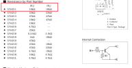

What value of VR should I try?RhanksNot quite right. The datasheet shows 10k resistor to base, then another 10k to ground, so some of the "base" current goes through the resistor to ground. Need to calculate currents with a voltage divider, and 0.6 volts base to emitter voltage to get right base current. It is the main reason transistor checkers show lower hfe than it actually is... I would try using a variable resistor, and increase voltage until collector current gets to 1 mA (1 volt across the 1k resistor on the collector) then measure voltage at the base and calculate the currents, base current being the difference between the (voltage drop -.6 volts) across one 10K resistor -0.6 mA (current across the 10K resistor to ground. Maybe use 5mA as that is the spec rating. The 0.6 volts is somewhat arbitrary - try calculating with .5 or .7 volts to get a range. YMMV
EDIT: pretty much what @gslikker suggested...
View attachment 3663749
View attachment 3663761
What do you have on hand?What value of VR should I try?Rhanks
anything between about 5K and 50K. You want to increase the voltage until the drop across the collector is 5 mA (or whatever operating point you desire, then masure the voltage on the base terminal, and calculate the base current to determine hfe.What value of VR should I try?Rhanks