
• The move to the new server is done. There are some software and database maintenance updates in process. This has us passing the hat around to help out. We appreciate any donations. Seriously, even a dollar helps. The payment page may be found here - https://www.audiokarma.org/support.html

Un-fixing a SX-626 power amp

MarkNJ

Active Member
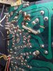
I acquired this SX-626 some time back in a no-op state. Finally taking a look at it, I noticed one of the leads on the power amp was broken (E4), and it looks like it had been recapped at some point. Also note the lack of a jumper for the negative points at the C13 / C14 replacements.


The strange thing that I uncovered, is that it seems that someone tried to "fix" some problematic pots by bypassing with a resistor and cutting the trace? I pulled a leg and it measured, 18 ohms. Why would someone do this? Desperation or brilliant engineering?
 

Attachments

  • PXL_20211115_212930042.jpeg
    PXL_20211115_212930042.jpeg
    173.4 KB · Views: 43
Register to hide this ad
Desperation.
Get a replacement for the pots, fix the hacked trace.
Looks like red blue black, 26Ω. Should be a 100Ω pot.
And the board needs a serious cleaning off of all that residue.
 
Parts arrived today. Unfortunately, I may have fixed the power amp only to uncover whatever else is wrong with this one.

No relay click on power on, so I check the voltages at the power supply.

Pin 3 57.7
Pin 5 30.5
Pin 7 12.0
Pin 10 23.1

Pin 7 may be a problem, should be 13.5, but Pin 10 is the obvious one for now (should be 13).

It doesn't look like any work was done on this receiver, outside of the aforementioned power amp board. I suppose I'm postponing the inevitable, and I should order all the caps that I'll ultimately need, and save on multiple shipping charges.

I think I'll get on with testing the transistors, diodes, and resistors while I have easy access to the PS board?
 
I may have spoken too soon. Looks like I have a different version of the receiver compared to the service manual that I've been using? My serial number is SC3809335, and I'm not sure if that makes this an early or late one.

Either way, my power supply board is marked AWR006C. The two different copies of the manual that I have show the PS board as AWR-029-A.

The only reference to the board I have and the voltages I'm seeing is this thread:

https://www.audiokarma.org/forums/index.php?threads/voltage-specs-for-sx-626.890555/#post-13228833

I'll keep hunting for another service manual. In the mean time, I'm all ears if someone has the copy I'm looking for, or additional troubleshooting suggestions.
 
Thanks @LesE!

Turns out, much ado about nothing. There was a blown protection fuse for one of the channels, which was making the voltages strange when I was trying to adjust the bias. One channel had the appropriate 57 VDC, the other ~20 VDC. I followed MTF's procedure for measuring the voltages at the output transistor cases, then across the appropriate resistors. Both channels right around 15 mVDC and it sounds good!

As I mentioned earlier, this will likely need to be recapped at some point, but it's good enough for garage duty at this point. Thanks again for the help @LesE & @merlynski
 
Back
Top Bottom