• The move to the new server is done. There are some software and database maintenance updates in process. This has us passing the hat around to help out. We appreciate any donations. Seriously, even a dollar helps. The payment page may be found here - https://www.audiokarma.org/support.html

Understanding power cords…

z-adamson

Addicted Member
Most older gear has a power cord like this…
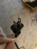
image.jpg

My basic understanding is that it does not matter which way you plug this in. It can go 2 ways into a typical 15 or 20 amp receptacle and it makes no difference electrically.

Now, what I am trying to understand is why it makes no difference and in what situations it does make a difference.

I am currently wiring up an amp and I don’t know for sure if I can use a power cord as pictured or if I need a 2 pronged plug with the neutral blade that is wider. I have the wiring of the amp figured out, just not the power cord.
 
Register to hide this ad
The cord shown (non-polarized) was the standard, replaced by the polarized cord. Most equipment runs on DC, and it shouldn't matter which way the cord is plugged in if it is a non-polarized plug, however I have found in rare cases (old tube amps & preamps) that a hum can exist until the plug is rotated and plugged in the other way.

At a minimum you should replace grounded with grounded, polarized with polarized. If you want to "upgrade" a non-polarized (like you're showing) there is usually no harm, I prefer to do so however using the (small) hot blade wired to the fused side of the equipment.

The only downside I can think of is that you can't plug polarized plugs into amps/receivers/preamps/etc. that have the earlier non-polarized recepticles (such as using a switched outlet for other gear etc.).
 
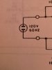
So when a schematic starts out like this…

image.jpg

…then a non polarized cord is fine?

So since amps run on DC, non polarized is the norm, makes sense.
 
The portion of the schematic you posted is worthless. OK, it does show the plug. But what are the other connections? Does it connect only to the primary of an transformer or is there a connection to chassis ground? It is best to show the full electrical circuit where current flows.

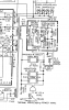
The schematic below from a Luxman LV-13 shows only connections from the power plug to the transformer primary and power sockets on the back. If the power sockets are polarized (I do not believe so, but I am not going to pull it out from the wall to look) then the power plug should match the polarization. Otherwise, it does not matter which conductor is hot or neutral.
Luxman LV-113.png

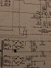
The schematic below is from a Realistic STA-2100D. One side of the power plug is connected to chassis ground through a resistor. That resistor is used to allow electrostatic discharges to dissipate to ground, whether it is the hot or neutral power connection. Ideally, the power plug conductor that is connected to the chassis ground resistor should also be the neutral side of the power plug. My STA+2100D has a polarized plug with the wide (neutral) blade connected to the chassis resistor. (It is sitting on the floor, waiting to be cleaned, so I looked.)
RS STA-2100D.png
 
I thought that perhaps since the schematic showing the plug without making any mention of hot or neutral may mean that it does not matter which is hot and which is neutral.

image.jpg image.jpg
 
So when a schematic starts out like this…

View attachment 2498320

…then a non polarized cord is fine?

So since amps run on DC, non polarized is the norm, makes sense.

With some gear you can measure between chassis and house ground and will see a "leakage" voltage reading. With a non-polarized plug you can measure it, then reverse the plug in the receptacle and measure it again. It is not unusual for one of those two measurements to be lower, possibly a lot lower, than the other.

When you identify the lower of the two readings, you could install a polarized plug/cordset with it connected to give the lower voltage reading, and being polarized plug you can then only plug it in the way it gives the lower leakage reading.
 
With some gear you can measure between chassis and house ground and will see a "leakage" voltage reading. With a non-polarized plug you can measure it, then reverse the plug in the receptacle and measure it again. It is not unusual for one of those two measurements to be lower, possibly a lot lower, than the other.

When you identify the lower of the two readings, you could install a polarized plug/cordset with it connected to give the lower voltage reading, and being polarized plug you can then only plug it in the way it gives the lower leakage reading.
So, meter set to ac volts, one lead on chassis and the other on house ground? As in, put the lead in the female ground pin of the receptacle on the wall?

Try it both ways with a non polarized plug. Whichever gives the lowest voltage reading is the correct way to have it plugged in.

Am I following you?
 
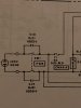
Another consideration is the position of the power switch(es) and main fuse(s). Since both sides of the line seem to be switched here (in the posted schematic), the postion of the fuse (which belongs on the "hot" side of the line) is what should determine which side of the plug gets connected to hot. Then, if the transformer was wired in to the circuit "correctly" (per whoaru's criterion) all will be well. But much variation exists as to whether these rules were followed or not.

Note also that vitually all "unpolarized" power cords actually do have a marking as to which side is supposed to go to neutral in the form of a line or rib on the cord itself (rather than on the plug). In theory, if you plug an unpolarized plug into a polarized outlet "correctly" (according to the marking on the cord) all will be well although in a fair percentage of cases this is found not be the case.
 
^^ What @audiotemp said. Many people do not grasp the fact that UL cords are marked, even if the cord cap itself is not keyed for polarization.
 
Another consideration is the position of the power switch(es) and main fuse(s). Since both sides of the line seem to be switched here (in the posted schematic), the postion of the fuse (which belongs on the "hot" side of the line) is what should determine which side of the plug gets connected to hot. Then, if the transformer was wired in to the circuit "correctly" (per whoaru's criterion) all will be well. But much variation exists as to whether these rules were followed or not.

Note also that vitually all "unpolarized" power cords actually do have a marking as to which side is supposed to go to neutral in the form of a line or rib on the cord itself (rather than on the plug). In theory, if you plug an unpolarized plug into a polarized outlet "correctly" (according to the marking on the cord) all will be well although in a fair percentage of cases this is found not be the case.
So in the schematic, if HOT went to the side with the inline fuse, that would be correct.

What would happen if the NEUTRAL went to the side with the inline fuse?
 
With some gear you can measure between chassis and house ground and will see a "leakage" voltage reading. With a non-polarized plug you can measure it, then reverse the plug in the receptacle and measure it again. It is not unusual for one of those two measurements to be lower, possibly a lot lower, than the other.

When you identify the lower of the two readings, you could install a polarized plug/cordset with it connected to give the lower voltage reading, and being polarized plug you can then only plug it in the way it gives the lower leakage reading.
I use a sharpie to mark the polarized prong rather than replace the plug. Just a short cut, lazy, no skill required way to do it.
 
Yeah, I did the same thing for a while on one of my tube amps. When I decided to rework a few things I replaced the cord with one having a polarized plug.
 
So in the schematic, if HOT went to the side with the inline fuse, that would be correct.

What would happen if the NEUTRAL went to the side with the inline fuse?
When the fuse blew, the set would still have a connection to hot just looking for a path to ground. That path could be you, your meter probe, or a stray wire. When the hot stops at the blown fuse, the unit is safer.
 
So in the schematic, if HOT went to the side with the inline fuse, that would be correct.

What would happen if the NEUTRAL went to the side with the inline fuse?

More correct from a technical/safety standpoint, but not necessarily does that inherently give lowest chassis to ground voltage.

Did you check and find one orientation of the power plug produced lower chassis to ground voltage than the other?
 
Back
Top Bottom