Greetings!
TL/DR: Could someone please help explain what abbreviations and weird deviation figures mean in the instructions below. For more detail read on!
I've been working on one of my Tandbergs TR-1020 (pretty much the same as TR-1000 or TR-1010) for the last little while. It's not an easy receiver to align since it has a real IF transformer filter strip, ratio detector and discrete transistor based stereo decoder. No specialized ICs, no ceramic IF filters unlike the rest of TR-10XX and TR-20XX lineup. Just tons of transistors and coils
Front end, IF, and detector alignment is Ok simply following the manual. Only caveat is that the manual doesn't tell one to use a Pi- attenuator of about 20-40 dB when injecting signal into antenna input. And crank-up signal generator output accordingly. This is to avoid RF cable acting as a big FM antenna...
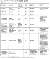
Stereo decoder alignment I'm still struggling with. I get the general idea, but the way desired generator signal instructions are written I just don't get it. See picture, for example:
Step 1 - 67 kHz dev. ca. 60 kHz
What does "dev. ca." mean? What am I supposed to do other than making sure the filter circuit output is the lowest at 67 kHz input?
Step 3 - 19 kHz dev 7.5 kHz
I can tune the circuit to peak at 19 Khz input, that easy. What I'm supposed to do with 7.5 kHz deviation? Sweep my signal 19 kHz +- 7.5 kHz and use XY inputs on my scope just like when sweeping IF filters with 10.7 Mhz? Or something else?
Step 5 - Right 1kHz dev.: 30-40 kHz and 19 kHz dev.: 7.5 kHz
This is the best one! It sounds like they want a pilot signal plus a test tone in the right channel, so basically an MPX encoded signal with dead left and a tone in the right. Great and I can sort of do it but what does 30-40 kHz and 7.5 kHz mean here?
Side note, if I get my right channel signal all the way to 30-40 kHz range (which should not be an actual stereo signal due to 15 kHz cutoff). Then I start observing some strong oscillations in 500 - 1500 Hz range in my output. I can tweak the same separation circuit to keep such oscillations low, but then my separation at 1 kHz test circuit is not it's best.
I recall there were a few AK members who are into Tandbergs and/or have good alignment expertise. Haven't had a chance to ask or comment before, but nice to meet you folks!
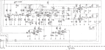
Stereo decoder circuit attached too.
Thanks in advance!
TL/DR: Could someone please help explain what abbreviations and weird deviation figures mean in the instructions below. For more detail read on!
I've been working on one of my Tandbergs TR-1020 (pretty much the same as TR-1000 or TR-1010) for the last little while. It's not an easy receiver to align since it has a real IF transformer filter strip, ratio detector and discrete transistor based stereo decoder. No specialized ICs, no ceramic IF filters unlike the rest of TR-10XX and TR-20XX lineup. Just tons of transistors and coils
Front end, IF, and detector alignment is Ok simply following the manual. Only caveat is that the manual doesn't tell one to use a Pi- attenuator of about 20-40 dB when injecting signal into antenna input. And crank-up signal generator output accordingly. This is to avoid RF cable acting as a big FM antenna...
Stereo decoder alignment I'm still struggling with. I get the general idea, but the way desired generator signal instructions are written I just don't get it. See picture, for example:
Step 1 - 67 kHz dev. ca. 60 kHz
What does "dev. ca." mean? What am I supposed to do other than making sure the filter circuit output is the lowest at 67 kHz input?
Step 3 - 19 kHz dev 7.5 kHz
I can tune the circuit to peak at 19 Khz input, that easy. What I'm supposed to do with 7.5 kHz deviation? Sweep my signal 19 kHz +- 7.5 kHz and use XY inputs on my scope just like when sweeping IF filters with 10.7 Mhz? Or something else?
Step 5 - Right 1kHz dev.: 30-40 kHz and 19 kHz dev.: 7.5 kHz
This is the best one! It sounds like they want a pilot signal plus a test tone in the right channel, so basically an MPX encoded signal with dead left and a tone in the right. Great and I can sort of do it but what does 30-40 kHz and 7.5 kHz mean here?
Side note, if I get my right channel signal all the way to 30-40 kHz range (which should not be an actual stereo signal due to 15 kHz cutoff). Then I start observing some strong oscillations in 500 - 1500 Hz range in my output. I can tweak the same separation circuit to keep such oscillations low, but then my separation at 1 kHz test circuit is not it's best.
I recall there were a few AK members who are into Tandbergs and/or have good alignment expertise. Haven't had a chance to ask or comment before, but nice to meet you folks!
Stereo decoder circuit attached too.
Thanks in advance!