• The move to the new server is done. There are some software and database maintenance updates in process. This has us passing the hat around to help out. We appreciate any donations. Seriously, even a dollar helps. The payment page may be found here - https://www.audiokarma.org/support.html

Upgrading a Hafler DH-101

Bob

Super Member
The DH-101 was Hafler’s first preamp after he founded Hafler. These were available from the late 70’s to the early 80’s. And they are still around – mostly in unmolested state. Therein lies the problem. Approaching 40 years old, the assumption is that they are all providing the same sound as they did off the manufacturing line.

I have had, over many years, several of the early preamps (DH-101, DH-100, DH-110) and they all differ in circuit topology, parts quality, and to a certain extent, sound quality. However after all these years, the electrolytic caps are well beyond their intended design life.

I have a DH-101 from a long time ago that was modified in the very early 80’s. This is before metal film resistors, boutique caps, and the general knowledge of caps and their “sonic” rankings. It has the optional head-amp, rack mount, and some third party black metal knobs. Not for sale and only occasional upgrades. I call this one the Master.

I did buy a DH101 off the bay that had problems. So I decided that I knew enough about DH101s that I could fix it. Took me weeks. Turns out the left output from the line section was intermittent. Signal going into the back panel RCAs was good but not getting through the RCAs. I eventually replaced the critical RCAs. The problem was that the crimp signal was not crimping. Simple – huh?

I then decided with all that time invested I would upgrade the dang thing. By upgrade I really mean blueprint. Like for engines – bring it back into spec. For the DH101 it meant replacing all the electrolytic caps (eCaps) with modern equivalents. Not being a slave to fashion any modern cap will do – just to remove the old caps to give the DH-101 another thirty years of life.

000-DH101.JPG
 
Register to hide this ad
here's what it looked like - as original as can be:

00-before.JPG

When I looked inside I thought it had been modified since there were metal films but I realized that there were some running changes made during the DH-101’s life.

I’ll summarize what I’ve found. It will all be about the changes and the eventual upgrading or blue-printing of the components in the signal path. I’m not interested in cosmetics, ding/scratches/scuffs/dongs, alignment of metal/sun/moon/stars, etc. spending too much time on non-essentials makes you crazy.

There was a DH106 upgrade kit offered for units with serial numbers below 1918999 and consisted of:

2 NPN BC413C (yellow dot) replacing Q1 (in both L & R Channels) MPS-A-18
2 PNP BC415C (blue dot) replacing Q2 (again L & R) MPS-A-6523
4 47R resistors replacing R10 and R11 (and for both L & R channels) which were 100R

The yellow and blue dots were to assist in replacement and do not show up in updated production units, for verification of the DH106 mods check R10 and R11 (either left or right channels) – these will be 47R if upgraded. If they are 100R then you’ll have to find the Q1 and Q2 or equivalents to upgrade your unit.
 
Later production upgrades – my list from observations, etc

10uf at C2, C11, C8, C20 – these were tantalums (orange, Blue) then NP eCaps (total 8 for two channels)

22pf at C9, C10 – I’ve seen ceramic disks, tantalums then finally micas (total 4 for two channels)

15pf at C12 ceramic disks, then tantalums, then micas (total 2 for two channels)

Early DH-101s use MPS transistors and later units used BCxxxCs. There are probably transistors that are out-of-production and may or may not have exact replacements (perhaps forcing a re-design of operating points, etc)

02-special note.JPG
 
Here’s the total upgrade

01-parts.JPG

Just the eCaps (note: read further down for diode rectifier changes in the power supply)

Qty ID original value note

4 C2, 11 10uf/3v NP use C8, C20 voltage rating (for cheaper lot of 10)

4 C8, C20 10uf/16 NP order 10uf 25v (16 is too low for +/-18v rail voltages)

4 C3, C4 220/6v P note P=polarized – replaced with 220/16 polymers

2 C5 470/16 NP

2 C17 220/16 NP

2 C24, C25 1000/35 P power supply – pre VR

2 C26, C27 100/25 P power supply – post VR (can use 150 or 220uf at 35v)

Replacing the others

4 C9, C10 22pf if ceramic disk or tantalum – use mica

2 C12 15pf if ceramic or tantalum - use mica

2 C13, C14 .1/25 (lower right in pix) use wima stacked film

Do note that you can safely bump to the next voltage rating for the caps since the VRs are +/- 18V so that any caps seeing close to this voltage should go to 25v ratings over any original 16v.

You can also save a few bucks and gain respect by going all NP (yes they will fit since modern caps are smaller and even if you up the voltage rating. See the power supply pix for relative size of new replacements). You can tell everyone green enhanced the midrange with the blue component, and redefined the highs with the yellow portion of the green. As you can see I do appreciate boutique parts.

But in all seriousness, Non-polar caps eliminate the explosions when you wire polars in backwards. (you can just imagine in Audioforum2037, they’re the non-geo-north orientations for better sound,…)

In the power supply I would not go up too much in capacitance since it would counteract the regulator’s ability to control transient voltages. (However, see the DH110’s power supply circuit with its 8 470uf Caps! – it stays on long after the power is cut). Post-VR C26/C27 is 100uf/25V and I have used 150 or 250uf at 35V.

Lastly, while you’re inside the separate power supply circuit, replace the 1N4002 (rated at 100PIV and 1amp) with UF4007s. You will need 4, and they all face (cathode-side) the front of the unit.

So the totals are:
20 eCapS
8 non-eCaps
4 uf4007 diodes

Before I realized that running upgrades used metal film resistors, I thought this unit might have been hacked so I decided to replace all the resistors with MFs. That way I know if the circuit values stayed true to the designer’s vision. As a note for all you numbers-matching-converts-from-the auto-world, the first DH101s were all carbon film and later ones had a smattering of metal films.
 
And here's the completed unit:

04-finished.JPG

You might notice some strange components at the C3/C4 plus everywhere they're supposed to be the 10uf NP cap (C2, C11, C8, C20). Yes, these are frankencaps, or bizzarro-condensers, or hydro-bros.

I saw them inside a Schiit unit and researched them. There were very few references to these organic electrolytic caps in low voltage audio circuits. One German guy said they were superior (and that's all I needed - short-circuit the armchairs and the professors - right?). The data sheets had more marketing than normal (longer life, less this, less that, etc). so I put on my lab coat and went to work.
 
03-paralleled-caps.JPG

Since the caps had to be non-polar and these didn’t seem to come in NP form (next year’s new product announcement) I decided to make my own. I glued a pair together, lining up the negative side with dots (blue ones for midrange purity). The other reasoning is that I wanted longer (non-negative) leads for any potential length issue. Crazy glue did the job. You could use the positive sides. Or alternate by channel or by stage then argue with the rest of us about proper orientation.

These were 22uf @ 25v Nichicons so they would be 11 uf in series. I’m not religious so I measured one of them at 10.7uf – close enough.

And replaced all eight 10uf NP caps. Also used 220/16 Nichicon organic polymers (polarized) for C3, C4 (total 4 for two channels). I chose the red-topped Nichicons for their grand expressions across the audio spectrum, you may want to try a different brand’s blue-topped organic polymers for their more revealing inner details. (I just know these fairytales/myths will get out in the open like smooth plate Telefunkens) - do note the orientation of the C3, C4 caps. Like all other eCaps they DO NOT LIKE being wired in backwards. There's a pop but no mushroom cloud. toss them since there's no apparent damage.

When I powered it up, there was an interesting phenomenon: the sound went on and off at about ½ second intervals for a few seconds. It was either the window when alien invasions occurred or there was some initial cap charging in my Frankencap experiment (just like cosmic rays and lightning in the movie). Using the SWAG methodology, it was probably a boundary-condition np-incomplete convergence of unstable conservation of parity. It turns out that these caps have huge initial turn-on surges. It's like a form of motor-boating found in tube amps but with a longer cycle.
 
Last edited:
Now you have my interest! I have a butchered DH-101 here in the shop. Basically it needs to be stripped and started over. The only mod I've seen is the update from Hafler, 106? I'll read your posts and go from there. Do you have a source for the push button covers? Mouser has some from C&K that might work.

Craig
 
now for some serious hot-rodding:

05-phono-front-end.JPG

C2 is now a NP organic polymer electrolytic capacitor with an orientation towards the output (you do realize this makes it sound better - right?). The phono loading resistor is a 47.5K Caddock precision film resistor. And a front-end of MF resistors - all at 1%. And more organic polymer electrolytic capacitors.

Is this nirvana? Or simply we should eat organic and now listen organically.

I suspect there will be an improvement over the NP eCaps found in later production 101s. Perhaps, not as much as boutique film parts or teflons.
 
Last edited:
One reason for the MF resistors is that the noise floor drops. Spooky black backgrounds (DSOTM is a great test - especially just before the telephone rings). Using MFs equalizes comparisons with the DH-100, DH110, and all the others that followed which used MFs in the audio chain. You can now compare them with the same level of componentry. Back in the day the DH-101 was built with 1/2W carbon films – rated at 5% which was probably all that was available at the time (at least to a price point). Later on, the MFs were available at probably a lower price point. 1/2w resistors are overkill. All the MFs I used are 1/4W.

Similarly, poly-something caps came along and changed the landscape. DH-101s went from ceramics, to tantalum, to NP eCaps. I’ve seen tube-style 630v 10uf caps inside these units. Super-large and awkwardly located. Also super-rare 10uf mica capacitors. There is enough space to mount these large caps where the head-amp goes or on top of the head-amp.

There may even be smaller 10uf/25-50v PET ones you could use. But perhaps even polyester is better than organic polymer eCaps. It will be up to someone else to prove or disprove this.

06-phono-section.JPG
 
Last edited:
now for the output section

07-output.JPG


Simple. The two red square caps are the Wima .1Ufs for C13, C14. Probably bypasses for the B+/B-
(too lazy to look at the schematic and no short-term memory = SWAG)

C20 is now the NP organic polymer electrolytic capacitors – meaning – input and outputs are matched, identical, and symmetric, etc. Your wife will love the fact you are now organic.

One of the only (there’s probably a couple not touched because they’re not in the signal path) carbon film resistors left is hiding between C20 and the pair of C13 and C14 and is the dropping resistor for the LED. Is it possible that we need a MF resistor there? Makes the sound better? Arm-chairs chime in.

Note the BLUE LED replacement. Final touch to sign your work. I recall the cathode being the right lead but you can verify with the flat side of the diode.
 
finally, the power supply

08-PSU.JPG

Recall these caps from earlier on. Try not to replace these with 1 farad caps from your car stereo. Ruins the VR’s day. There are unused wire assignments on the PS board – intended for the headamp.

If you are a tinkerer and must change the fixed voltage VRs to adjustables, look at the DH-110’s power supply. Or buy a pre-built one and mount on the left side of the cage and migrate wires over (leaving the original in – unmolested – just in case). The argument regarding noise levels is best left to armchair guys.

Note that the fuse is a 1/16A 3AG slo-Blo (for 220+ volt operations it’s a 1/32A). My master DH-101 with a head-amp blew one so I suspect the 1/16A is marginal for both. These are expensive and I thought I saw that LittleFuse might have discontinued the very low-end but I could be wrong about this (I get confused very easily and my short-term memory is, indeed, very short). So, no screwdrivers, probes, or pointy metallic things inside the unit – ever. Use insulated probes with clips then turn the unit on.

For example, NO need to determine whether the regulators are working by live probing inside the enclosed area. There are two points on the main board where B+/B- are wired to. Follow the wires.
 
The back panel

Where my problems with this particular unit began. As I mentioned earlier, the left output was intermittent. I traced it to a non-crimping crimped signal connector on the RCA strip mounted to the back of the DH-101.

I replaced the critical RCA connectors (from left to right: Output, Aux, Tuner, and Phono 2). Took a long time because removing the tab-mounted connectors was a royal pain. And I didn’t want to change out all the RCA connectors. But if I did, I would label all the wires, cut them off, and remove the flimsy mounting board. I would use a strong inert (non-conducting) board, drill holes (matching the mounting diameter of the replacement RCA to prevent slop – after all we are using organic capacitors), and with shielded cable for all. That would have added another couple of months to this project but I have seen some others do it – probably in days.

09-rear.JPG

But in fairness to my laziness, I don’t care about cosmetics. I could repaint the unit, after repairing any damages, scuffs, etc but I’m here to listen not to look at it.
 
A general note about the MF resistors.

As you can see from the pictures, most of the 1/2W carbon film resistors have been replaced by 1/4W metal films.

In case you’re interested here’s a list (do verify with your unit and whatever accurate/inaccurate version of the manual you have):

R1 47K Yel,Vio,Or
R2 22K red,red,Or
R3 22K
R4 150K brn,Grn,Yel
R5 150K
R6 22K
R7 240 red,yel,brn
R8 22K
R9 10K brn,blk,Or
R10 100 no DH106
R11 100 no DH106
R10 47 with DH106
R11 47 with DH106
R12 470 Yel,Vio,brn
R13 11K Brn,Brn,Or
R14 130K Brn,Or,Yel
R15 100K brn, Blk,Yel
R16 100K
R17 22K
R18 82K Grey,Red,Or
R19 22K
R20 82K
R21 100 Brn,Blk,Brn
R22 100
R23 10K
R24 1K Brn,Blk,Red
R25 10K
R26 1K
R27 470
R28 4.7K Yel,Vio,Red
R29 1K

Do note that these are for each channel. So if you order these, follow the color codes: each value is listed once and note R10 and R11 are either 100R or 47R (depending on whether DH106 is missing or not). Double the quantity for both channels.
 
Last edited:
There are other resistors on PC-2, PC-3, and that lonely old Carbon film for the Blue LED:

R30 1K
R31 1K
R32 2.7K
R33 2.7K
R34 10M
R35 6.8K

I generally don’t swap out the carbon films when it’s a buffer for the tape machines. I rarely see Japanese tape decks with other than carbon films. So why bother with the black sheep.

The R35 is the LED dropping resistor. Enough said. Order a blue LED.

Some last minute notes on upgrading. My technique is to replace one at a time (foregoing the remove them all and remembering what went where) for several reasons:

1. For the most part, there’s no parts stenciling on Hafler boards so you’ll need the parts layout diagram in front of you and even better, a picture of the board with all the parts labelled

2. Replacing them one at a time, means you can verify the removed part’s value and pull its
equivalent value replacement part from your bag of parts.

3. You can immediately plug said replacement part into a tester or VOM/DMM or capacitor measurement device to verify it’s the correct value.

4. For capacitors that are polarized, you can use a marker on the board to indicate polarity. I usually add a + sign. You should still do this even if you go with NP caps.

5. Same for diodes if it’s not already done for you – Hafler does add polarity stenciling on top of the board for diodes, caps.

6. The only time you can remove more than one part is if they are all the same - like caps. Or the rectifier diodes in the power supply.

7. One-at-a-time means no misplacement of parts – you see this all the time in the forums when
someone removes all of them and confuses a 470K part for a 4.7K part and spends a month looking for the mistake – risk reward ratio is wrong.

8. Earlier I listed the color coding of the DH-101 resistor set – this is for id’ing the resistor to be removed. Then measuring the replacement to avoid reading the super-thin color markings and/or assuming it’s the right part. Measure old, measure new – don’t trust all the parts are bag labelled correctly – maybe you picked up the wrong bag. Saves you days tracking mistakes down (and how do you do this? Original and final parts count must match – leftovers or missing parts = oops).

So, I love the Haflers. This upgrade/update/blue-print will keep it going and maybe for another 40 years.


Please feel free to comment, correct any omission, errors I may have made – I assure you it is a sin of omission or overlooking, or forgetfulness.

And again, thanks to all of you AKs that have freely given your advice, knowledge, help, and support.
 
@llwhtt

great! one of the few times you can revive the dead!

my notes on this.
1. rare to have a unit totally destroyed - try all the inputs and all the outputs (tape outs, equalizer outs, and preamp out)
this will tell where if any the problem might be. localize to phono or line section and left and/or right channel after that.
2. most of the time it's the wiring (kits - check all the connections) board to backplane, the RCAs, or the fuse is blown, or something in the power supply.
3. if everything works and there's noise or distortion, either temporary or full-time, then determine whether it's
the phono circuit or the line level, then check the caps. replace them - there's a grand total of 8 eCaps on the board outside the
10uf coupling caps. you could pull these from the line stage (higher voltage rating) and test the phono section. Probably
better to just order 8 10uf NP eCaps and the other 8 eCaps.
4. I haven't seen any that needed reflowing the solder joints, in fact its the opposite, they are in good. Although I'd use the pencil poke
trick to verify.

post a picture of the inside and PM me your physical address for a free blue LED if you need one.

thanks for the praise, I do this to return a favor to all those on AK that help others.

Bob
 
For some reason the power xfmr and power supply got moved to a different location, outside the normal compartment it normally resides. It was done rather sloppily with pieces of zipcord. Also the 100 Ohm resistors were replaced with 47 Ohm resistors that are way too large for the board. I've already stripped the boards clean and started repopulating them. It's on the back burner for now as I have paying work that needs to done.

Craig
 
Great thread. I'm a Dynaco/Hafler fan myself. Those organic caps are interesting, when I first saw the photos I thought they were some kind of factory multi-section cap. I then read the post and had an aha moment when you said they were crazy glued together. I'm interested in your listening impressions with the preamp and maybe some comparisons to other units that you might have. Since the DH101 was the first Hafler preamp, would it be safe to say it's kinda a PAT6?:idea:
 
@rshep

I'm finishing up the 101, then let in burn-in. I finished this earlier but had a volume imbalance so
I'm prepared to scale Mt Everest with scope, signal gen, vitamins, and prayer. there's no easy
fix like a bad muting circuit as in the 100 and 110. I just finished the 100 and 110 so the 101 is next.

I will do some critical listening once I figure it out. I am also hoping those serialized organic eCaps
may have something to do with the issue - it could be simply it needs a long time to charge up
or burn in these, or perhaps even leave them on for a long time before listening.

I do have a "master" 101 that is my main preamp - too much work went into this to consider
anything else.

I do agree that the 101 was their opening masterpiece and with upgrades and "newer" parts
they hold their own with the 5-figure ones. On top of the easy to maintain circuit design and
layout, they make for good test beds, learning units, and ultimately great listening.

The biggest wow factor was the replacement of all the resistors with MFs. then the better caps.
I think the resistors dropped the noise floor so the music pops into the soundstage, and the caps
give it that living breathing tone we all look for.

Bob
 
@llwhtt

that transformer should be in it's "cage" - there's no shielded cable anywhere inside and
the wires are not always twisted nor crossed at 90 degrees - adjacent bleed through is
right there waiting.

good luck with your other work and looking forward to your rebuild of the hafler from hell.

Bob
 
Thank you for posting this excellent thread! I am currently also recapping a DH-101 and I am trying to decide which caps to use for C2, C11 so I hope this is not perceived as a total thread hijacking.

This DH-101 specimen appears to be original unmolested, and possibly factory assembled. I purchased it about 6 years ago for $100 and have no clue as to its origin, the serial number is 1834046.

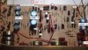
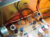
The manual lists C2 and C11 as 10 mfd, 3V, Tantalum. In the following picture I have circled all four pairs. They are wired in series by the board itself. The existing orange tants are definitely polar and are arranged on the board with the positive leads tied together. See photo below:

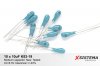
I purchased some Nichicon gold electrolytics (polar), and these are 10 mfd, 16V. I was going to go the Frankencap route which should yield an installed 5 mfd capable withstanding 32V (see left in the photo below). On the right are some Niobium caps. I paid 5 euros for 10 of these to some ebayer in Lithuania, and they were described as '10uF 6.3V K53-19 High Quality Niobium Capacitors. Rare!'. I measured both and found the lytics to be close to 10 mfd and the Niobiums closer to 12 mfd. So installed, I should achieve 6 mfd capable withstanding about 12V.

I invite anyone watching this thread to chime in here... What is your opinion as to the best choice? I have read that these coupling applications should be done with good quality films. I have read in this thread and in others that lytics are a great choice. I can't find anything on whether Niobiums are good for audio, and I have also read that it is not good to over-rate the caps for voltage by too much and that a rating of 30 to 60% of the actual voltage is ideal. Finally - in several threads on this forum I have read that getting the value down to 4,7 mfd or thereabouts would improve bass (this appeals to me for sure).

Any input here would be much appreciated!

Best regards,

David

Hafler.jpg Caps.JPGNiobium.jpg
 
Last edited:
Back
Top Bottom