• The move to the new server is done. There are some software and database maintenance updates in process. This has us passing the hat around to help out. We appreciate any donations. Seriously, even a dollar helps. The payment page may be found here - https://www.audiokarma.org/support.html

Use chassis-mount resistors in high voltage service?

Dave451

AK Subscriber
Subscriber
Here's a component question I have wrestled with a bit. When choosing power resistors for voltage dropping in high voltage circuits (up to, say, 500VDC), wire wound resistors have been the norm in tube gear over the years, particularly the "cement" or "glass/ceramic" types. More recently, the chassis mount types have been become available and seem like a good option, particularly their ability to dissipate heat through chassis mounting or other heat sinking, instead of dumping it into the under-chassis space and perhaps heat-stressing other components.

This particular resistor turned up in a BOM and looks to be a quality choice:


I have purchased a few of these types, but am reluctant to use them for HV because of the "maximum working voltage" spec in the datasheets, such as this one. The MWV for this one (and many of these type) are shown on the sheets as a formula: MWV = square root of (Power rating x resistance). For the above resistor rated at 5W and 1500 ohms, this works out to only 87V!

The data sheet shows a "dielectric withstand voltage" of 1000V or 4500V, depending on type for a short period of time.

So, my main question is: is the maximum working voltage for the absolute voltage in the circuit or the difference in the dropped voltage? Would this type resistor be appropriate for dropping voltage in a circuit with a 450V working voltage and startup surge voltage of 500V+?

Also worth noting is the operating temperature power dissipation limit that might knock 20-30% off the power rating at tube gear operating temperatures.

Are these resistors appropriate, then, for HV dropping service in tube gear?

Dave
 
Register to hide this ad
Id use it at 500v.

The limit is determined by the point at which there's so much potential across it that it arcs to the case.

If you're wanting some insurance slip a bit of heat shrink over the lead after soldering.
Also:
Earth your chassis!
 
Ive used them without issue. I use thermal grease between the resistor and chassis. Shrink tubing the ends is a good idea. What scares me is when I see these used and they aren't attached to the chassis. They won't dissipate the like they should.
 
Yeah, unfortunately it looks like they don't have a datasheet spec for exactly what you're looking for. Maximum working voltage is clearly just ohm's law (they're trying to idiot-proof it) and relates to the voltage across the resistive element, not the isolation between the resistive element and the case. Dielectric withstand is not explicitly for continuous usage, and the relationship between dielectric withstand and continuous working voltage tends to vary by product and manufacturer. For instance, I've asked some transformer manufacturers and continuous working voltage to ground tends to be around 1/2 to 1/3 of the withstand test voltage (e.g. a filament transformer with a 1500 volt hi-pot test is only rated for 500 v working to ground).

It's possible this is a spec they have and just don't disclose on the datasheet, so you could reach out and ask for the maximum continuous working voltage between the resistive element and the case.
 
dielectric strength should be the voltage to case. Thats the one you have to worry about.

that formula is just an ohms law power dissipation thing. 1500 ohms and 87 volts is 5 watts. Doesn't seem to have much to do with any actual voltage rating of the resistor.

also that would be drop across the resistor, not relative to ground or anything like that.
 
The specifications shown for dielectric voltage are not the maximum rating. They only describe the test conditions. Also note that these voltages are stated as RMS. That means the resistors withstood peak voltage 1.414 times that amount without arcing to the case. They should be perfectly safe at 500VDC, but as commented earlier, be sure to earth the chassis.

Screen Shot 2025-05-25 at 10.53.45 AM.png

Jack
 
Those types are really available at 50W and above ratings, I typically at least double the rating needed in high-dissipation situations. I don't have any of these types under 25W and no problems operating at 400V in my amps.
 
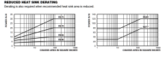
I had been tempted to use these, too, but had a look at the heat sink requirements and ended up using them only for 8 Ohm dummy loads. Have a look at the heat sink requirements at the top of page three of the link included in the OP's message (or here):

POWER RATING
Vishay RE resistor wattage ratings are based on mounting to the following heat sink:
RE60 and RE65: 4" x 6" x 2" x 0.040" thick aluminum chassis
RE70 and RE75: 5" x 7" x 2" x 0.040" thick aluminum chassis
RE77 and RE80: 7" x 9" x 2" x 0.060" thick aluminum chassis

I had always interpreted this to mean that these resistors needed more than just the average metal chassis to dissipate heat and stuck with appropriately rated ceramics mounted above the chassis when possible.

I could suggest vertical cement-filled ceramics for both heat dissipation and a decent voltage rating for ten watt and up units:

https://www.ohmite.com/assets/images/res-tww-twm.pdf?r=false
 
I had been tempted to use these, too, but had a look at the heat sink requirements and ended up using them only for 8 Ohm dummy loads.
Not a fan of heating the chassis, even when it's an adequate heat sink. If that much power needs to be dissipated, I use components that can be mounted above the chassis as you suggest, or I redesign the circuit for better efficiency.

Jack
 
There is a de-rating based on available heat sink space, right down to no heat sink at all though with nothing I think its like 15 or 20% of the marked rating.

Sane design doesn't run resistors more than about 50% of their marked rating anyway so its just a little more de-rating on top of de-rating.

I use them but most of the things I need don't dissipate that much power, and I'm using that form factor for mounting convenience as much as anything else. If its replacing an old sand resistor it probably just gets a like for like swap but when the original part is missing/broken/never there I might use a chassis mount one if it makes life convenient for me.
 
also for whatever it may be worth, I have a 10 watt 33 ohm chassis mount in my Pilot SA-260 where it sees a good 500 volts at power-up. been in there for years, doesn't seem upset with life.
 
Just for clarity, the heat is a function of the power dissipation, regardless of resistor design or model, no? If your design calls for a resistor dissipating tens of watts, there is going to be heat to deal with, so deal with it whichever way you enjoy. It doesn't have to do with the resistor model.
 
The HH Scott amps have/had those vertical ceramic resistors, but they have a tendency to crack or break when bumped too hard. Some folks use finned heat sinks attached to the exterior of the chassis, with a resistor of the type shown, mounted to the heat sink through an opening in the chassis. Aesthetically I feel that makes an amp look less 'tubular' but I would do that myself, choosing function over form, safety over 'pretty'. :)
 
For anyone else interested in obscure electrical parts, a (more) modern version of the old vertical ceramic resistors is the Dale PH series. Not in production anymore and was probably quite expensive new, but they accomplish the same thing: dissipating the heat outside of the chassis. Plenty can be found on auction sites.
 
Just for clarity, the heat is a function of the power dissipation, regardless of resistor design or model, no? If your design calls for a resistor dissipating tens of watts, there is going to be heat to deal with, so deal with it whichever way you enjoy. It doesn't have to do with the resistor model.
Yes, but the chassis mount resistor power ratings are only with a heat sink of whatever size the datasheet says. Without the heat sink or a too-small one the rating is lower than whatever it says on the body of the thing.

1748229717233.png

There are also de-ratings for ambient temperature.
 
One of my Allen Organ amps, model 75, has this version of the Dale PHs:
1748229491105.png

They do take up less space than the sand types used in the others. I think they have a late 1960 date code (Too lazy to get up to look.).

When I was at the planning stage for the rebuild of my IPCs, I had thought about using the Vishay REs if only because I thought it prudent to add a little dissipation headroom until I saw how much room the heat sinks would take up. Ultimately, replaced the tubular ceramics with the same model and wattage, Ohmite 270 series at 25 watts, but mounted on top of the amplifier in cages. Thermal management at its best - if you have the room.
 
Doesn't the PH series also rely on conducting the heat to the chassis? I seem to remember reading years ago that chassis size affects the rating. Maybe I'm thinking of something else, don't have a data sheet now.

Jack
 
Yes, but the chassis mount resistor power ratings are only with a heat sink of whatever size the datasheet says. Without the heat sink or a too-small one the rating is lower than whatever it says on the body of the thing.

View attachment 3512166

There are also de-ratings for ambient temperature.
Sure, I don't understand the "only" part. They need to be used as intended and spec'd, and the easy way to deal with it is to use a rating where the derated power is more than enough. I'm not sure what applications people are needing resistors to dissipate more than 10W in a tube amp, barring wildly exotic stuff. It seems people like to design with regulators very frequently that require more significant heat sinking than discussed here, and they seem perfectly happy to use heat sinks in those instances.
 
meaning that if you buy a 30 watt rated part and don't mount it to a heat sink, its really a 10 watt part. So long as that part is understood its fine. Just don't try and use it like a 30 watt part.

Solid state regulators aren't any different. There is an amount of power they can dissipate with no heat sink, and an amount of power they can dissipate with a heat sink of some dimensions, with a range in between depending on what its actually bolted to.
 
Back
Top Bottom