
• The move to the new server is done. There are some software and database maintenance updates in process. This has us passing the hat around to help out. We appreciate any donations. Seriously, even a dollar helps. The payment page may be found here - https://www.audiokarma.org/support.html

Valve AM tuner fault

QSilver

Super Member
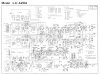
I've been working through a Pioneer LX-420A valve receiver. I've replaced the electrolytic capacitors and got the FM MPX working again along with the amplifier circuits. But I've got a problem with the AM tuner.

It looks like when you switch over from FM to AM, the FM front end is switched out together with V10 and the AM front end is switched in, together with V14 - a 6BE6/EK90.

The problem is, that FM works fine, but switching into AM causes the tuning needle to peg to maximum and the tuner goes silent. No hiss or anything.

I've checked resistors around V14 and values look ok. Am I looking in the wrong area or missing something? Where do I go from here?

The LX-420A I think has some similarities to the SX-34B if that helps at all. I think mostly the differences are that this unit can tune into FM/AM/LW/SW
 

Attachments

  • LX-420A-S.jpg
    LX-420A-S.jpg
    162.1 KB · Views: 8
Register to hide this ad
pegged needle usually indicates very negative AVC line voltage. Only reason that should happen is a bucketload of signal through the IF strip, or maybe if one of the detectors is toast. I have had oscillation problems in an IF strip cause this, but I'd check the diodes first. The schematic shrinks down fairly badly on here but it looks like the AM detector stuff is between the first and second 6BA6 tube. One should be the audio detector, the other should be feeding the AVC line and the meter. I can see there are two, but I can't read the part numbers. AVC ties back to the grid of the 6BE6 and it also goes to the selector switch.
 
Ah, yes, I didn't realise how much it would be compressed. I tried a PDF to begin with and it was too large at around 3MB. Here's a section of it in higher resolution focusing on the AM sections you mentioned. I wondered if the AM switch could be dirty? Failing that the diodes your indicating should be tested are D1 and D2?
 

Attachments

I've looked for D1 and D2 but there might be a difference between this and the schematic. I've found D1, but D2 is connected to Pin 6 of T2 or T3 The problem is, neither of these have a Pin 6...

D1 tested open so I've replaced it with a 1N4148. No change in behavior though.
 
More information. I've checked voltages on V10, V11 and V14. Pin 5 of V10 and V11 are 92V and 95V respectively. V14 Pin 6 is supposed to be 63V but is actually near double at 110V. Does this mean the valve is not conducting as much as it should be?

Pin 5 of V14 is 145V
 
D1 I think would be a germanium, so probably 1N34a. Don't know that its going to make a massive difference honestly. Forward voltage drop is the main difference, about 0.25 vs 0.5 volts.

pin 6 is the screen, that shouldn't be seriously affected by current flow through the tube with only a 25k resistor but it will be affected somewhat. If the AVC line is hard negative the tube won't be conducting much of anything though, so that might be why. Measuring the voltage at R63 and R64 would tell you whats going on there. The two large resistors between that point and the grid will be enough to make even a 10M meter load skew the results, but back closer to the source the meter loading won't affect things by much.

also possible there is no complete circuit for the cathode and/or grid. Not sure what position the switches are drawn in, but it looks like S1 5/6F (what a name that is!) switches the cathode between L4 and L5 depending what band its on. If one of those coils or that switch contact is open, V14 won't do anything. Looks like the other side of that switch flips the first grid between those two coils as well to make the oscillator function.
 
Yeah, I wondered about the forward drop of silicon vs germanium but figured a working diodes of any type is better than a open one.
Can you tell me what or where the AVC line is? I'm not sure how to identify it. IS it the feed running through R91 between R64 and T1 pin 6?

As the S1-4/6R is in a position that looks like the meter lamp is not powered, I'm guessing the switch is in either the Aux position at the end of the switch, or one of the other non-tuner positions on the other end of the switch such as Tape or Phono. I think perhaps in the Aux position just before it goes into LW would make the most sense?

I will try to find the wires to L4 and L5 and see if the switch is working with a continuity test. Something around the switch does look like it might be a bit odd but I'm not sure just yet...

Would any pictures of the chassis help?
 
Last edited:
Continuity seems to check out on the switch wafers 6/6F and R and 5/6F. Though it seems L4 and L5 are both put into circuit on AM and LW.

It also seems the AM/LW meter feed is coming directly from V10 Pin 7. Does that make sense?
 
Last edited:
avc is generated by D1, voltage comes through R63 and eventually ends up at pin 7 of the 6BE6 by way of R87 and R91 it looks like. I don't know exactly whats in the black box of FM front end, but I'm assuming there is some connection between the two IF pins to pass AVC voltage and IF signal through to the grid of V10 as well.

If the meter runs off cathode current through V10, then what may be happening is there is in fact no connection between those pins on the FM board. No negative grid voltage would run full current flow through V10, and that would peg the meter. Also wouldn't receive anything. Any chance you can just jump those together to see if it does anything? The output of T1 has to get to pin 1 of V10 somehow. I don't know where the meter would be connecting though, it doesn't appear that anything leaves V10 on the schematic.


once in a while its called something different. AVC is Automatic Volume Control, but sometimes its Auto Gain Control or Auto Level Control. I think some of that was marketing, people called it different things for patent reasons or whatever but its all the same thing. As signal increases, gain is decreased to keep it from overloading the detector. With AM, high signal = high volume so auto volume control. The ancient radios before this could go from a very weak signal to ear-bleed volumes as you roll through the dial. Pretty annoying when using headphones.
 
As it happens, I have the schematic of the frontend too! So the mystery is revealed.

Thanks for explaining that. Maybe there is a bad solder joint inside the FM frontend? Its lid is tacked down with some solder joints at three points. I could open it up and check everything is ok in there? Otherwise its safe to jumper across the connection from T1 pin 1 to Pin 1 of V10? I could measure the voltage of Pin 1 V10 and check for continuity between these T1 and V10?

The meter connects as follows. Meter connects through into Pin 11 of S1-4/6F. From there, it goes to Pin 10 then directly via a yellow wire to Pin 7 of V10. The module of a 68R resistor and 0.01uF cap is also between Pin 7 and connected to chassis.

They must've changed the design slightly at some point as D2, R61, C35 are completely missing. and Pins 5 and 6 of T3 are unpopulated with no solder lugs.
 

Attachments

Did some checks - there is continuity between T1 and V10 pin 7. I checked the voltage present when AM is on. -0.2V. Could that be the issue?
 
seems to me it should be more negative than that. What do you get back at R63 ? Just wondering if maybe one of those high value resistors has gone open.

front end schematic looks sensible. The 10.7 mhz IF can looks like a wire to a 455khz IF and a little bit of DC grid bias so it just passes right through.
 
I haven't had time to measure voltages in the circuit today, but I've checked the resistance of R63 and R64. They measure 52K and 111K so they've exceeded the 10% tolerance. I'll check voltages tomorrow before I replace them and then again after. What region of negative voltage are we looking for?

Just trying to work out where the negative voltage comes from... at a guess... is a voltage pump formed between D1 and the two capacitors around it?

I've also looked into the differences of my unit vs the schematic. Pulling up the schematic for an SX-34B shows the AM signal meter wired EXACTLY as mine is, and the diode D1 is said to be a 0A79 which is what I found in my unit - not the 1S34 that is written in the schematic. I don't think it matters much right now but could be important.
 
the ones I'd be more concerned about being completely bad are R91 and R87. If R91 in particular went open you'd get no grid voltage at either V10 or V14. The tolerances here can be pretty sloppy but they can't be totally open circuit.

Voltage will depend on signal but somewhere in the -1 to -15v or so I'd think. The weaker it is, the closer to zero.

D1 is just a detector. It rectifies the signal and the caps to ground average it out to be just DC voltage rather than an audio signal.
 
just out of curiosity, do you have a signal generator that can put out 455 khz, maybe with modulation ?
 
I've already replaced R91 & R87. I've replaced the other ones too now. This hasn't really changed the voltages a lot. The highest voltage along the line is at Pin 7 of V14 @ -390mV Adjusting the tuning dial does make this voltage move around a little but not a lot.

Bottom of the scale is getting to -400mV and it reduces as I go up the scale

I do have an FM/AM frequency generator and modulator so I would guess that will easily generate 455kHz? Moudlation at 400Hz or 1kHz.

Also have an MPX generator - no use for AM of course but still.
 
see if this does anything

set the generator to 455 khz, modulation at whichever frequency you prefer
ground to chassis, + to the pin on the FM front end with C33 attached to it, through an 0.01uf or so cap. Value not critical, whatever you have on hand. Or honestly you can probably clip to the wire insulation and have that couple enough signal in.

See if you get the tone through the speaker. If the IF amp and detector are working, you should. It should also show something on the signal meter.

also I probably should have asked this earlier but are you sure the 6BE6 is good? Since FM works I'll assume the 6BA6 is fine but if the 6BE6 is dead, this won't work either.
 
Some good news. Yes, Connecting 455kHz to the front end as you suggested does give me a clear tone. The meter is still high up the scale as it was, however if I adjust the frequency up to 465kHz themeter deflects a little higher, higher again at 475kHz and then drops away again if I go higher again. So I suppose the IF amp and detector are working?

I have no idea if the 6BE6 is good or not. I had wondered if it was bad as the voltages I've been reading don't match up to what the schematic says should be present. The heater is working and it does get warm.
 
Some good news. Yes, Connecting 455kHz to the front end as you suggested does give me a clear tone. The meter is still high up the scale as it was, however if I adjust the frequency up to 465kHz themeter deflects a little higher, higher again at 475kHz and then drops away again if I go higher again. So I suppose the IF amp and detector are working?

I have no idea if the 6BE6 is good or not. I had wondered if it was bad as the voltages I've been reading don't match up to what the schematic says should be present. The heater is working and it does get warm.
Get a small AM radio near the tuner and tune around on both until you hear something on the second radio associated with tuning the Pioneer. If nothing after several attempts, the local oscillator in the tuner is probably nonfunctioning.
 
Back
Top Bottom