• The move to the new server is done. There are some software and database maintenance updates in process. This has us passing the hat around to help out. We appreciate any donations. Seriously, even a dollar helps. The payment page may be found here - https://www.audiokarma.org/support.html

Valve Amplifier valve identification

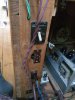
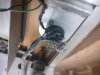
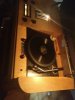
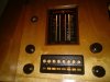
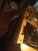
Hi Gadget yes the open socket is a phono input which for me is one of the best things as i can add any input source and thats cool as i can play youtube songs or playlists, cd etc and the sound is really nice (for now) con is that it is exposed and was causing a lot of hum from not being ground properly at a certain point. What i would like to do with it is to move it and insert it within the top of the cabinet so everything is underneath. There are many other inputs/outputs on the side panel were i can add external speaker and at the bottom is a rectangle power socket that i can add the small reel to reel amplifier to it as it has playback and record but again that is another thing. I am not sure on a couple of other inputs. I am still not happy with the radio quality etc and i am thinking the missing valve is the issue- i added a power valve to one socket and it seemed to be ok but maybe the missing valve has something to do with the tuning or the Em34 magic valve that is not working. I have ordered another so will test if it is the valve or something else. I was also aware of the yellow wire coming out from the speaker (in pic) that doesn't do anything but is there. I was hoping the tech guy would have solved the pre am missing valve but am thinking he may have been taking a slight shortcut. The other guy i had taking a look seemed to want an extortionate cost and many months so i am slightly cautious and may take my time and enjoy the processes of elimination and learning until i can get it sounding at least like i think it can.

Obviously this is a learning process and i am not skilled at rewiring or soldering although i am skilled at listening and observing i think i can manage in time. If anyone knows where i can purchase modern cabling that will replicate the old would also be very helpful as i do need to change the mains and speaker cabling....
 
Last edited:
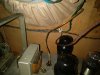
added pics i forgot to add...
 

Attachments

  • IMG_20180510_191802.jpeg
    IMG_20180510_191802.jpeg
    75.9 KB · Views: 14
  • IMG_20180510_191809.jpeg
    IMG_20180510_191809.jpeg
    102.9 KB · Views: 26
  • IMG_20180510_191813.jpeg
    IMG_20180510_191813.jpeg
    91.9 KB · Views: 13
  • IMG_20180510_191823.jpeg
    IMG_20180510_191823.jpeg
    89.4 KB · Views: 14
  • IMG_20180510_191831.jpeg
    IMG_20180510_191831.jpeg
    51.4 KB · Views: 14
  • IMG_20180510_191835.jpeg
    IMG_20180510_191835.jpeg
    50.6 KB · Views: 14
Good to hear progress. Although there is a view, especially in the UK, that one should try and retain as many original caps as possible, I think that often just delays repairs. I once had a Heathkit power amp that only worked when I finally replaced the last remaining cap, which was a silver mica one.
Micas are normally reliable, but I've replaced bad ones in a military communication receiver and an oscilloscope time base.
 
Micas are normally reliable, but I've replaced bad ones in a military communication receiver and an oscilloscope time base.
Hi Pio, what do micas do or look like in a receiver? Or are we talking about wires? Apologies for my lack of knowledge...
 
Hi Pio, what do micas do or look like in a receiver?
Usually small square or rectangular flat moulded cases with axial leads and color dots, something like small dominos. There are some vintage paper capacitors that look like larger versions that are almost always gone bad.
Silvered mica dipped coating examples look like hard chocolate candy with two wires from one edge side.
 
Interesting that it has open sockets. Are they wired up underneath? Just wondering if maybe they were used to supply power to some other component that is either no longer present, or that the original builder planned to add but never did. Thats a lot of the trouble with custom homebrew gear, if you don't have the builder's documentation or the builder to ask questions of, you sort of have to reverse engineer it and figure out what you have. Some people enjoy the technical challenge of that (I do anyway) but its very time consuming.


If the amplifier works, it sounds like there are issues remaining on the tuner.
Your right, it's been a challenge, the tuner is an issue. Do you know how the magic eye works ie...is it connected to the signal or does another valve power or contol it?
 
Last edited:
Usually small square or rectangular flat moulded cases with axial leads and color dots, something like small dominos. There are some vintage paper capacitors that look like larger versions that are almost always gone bad.
Silvered mica dipped coating examples look like hard chocolate candy with two wires from one edge side.
How do these affect the tuner? And how would you tell if they are faulty? Thanks for the info
 
Your right, it's been a challenge, the tuner is an issue. Still after two tech guys taking a look they both couldn't tell me what the valves could be or do. Do you know how the magic eye works ie...is it connected to the signal or does another valve power or contol it?
It's technically simpler than one might think.
The magic eye has it's own drive amp unit, it requires heater and HT voltages plus agc drive from the AM detector stage. An FM tuning eye is similar but the detector drive connections differ somewhat.
 
How do these affect the tuner? And how would you tell if they are faulty? Thanks for the info
These caps can cause erratic or total malfunctioning if bad. Used typically as part of a tuned circuit, can cause noisy, erratic, or total malfunctioning, same effects used elsewhere.
 
It's technically simpler than one might think.
The magic eye has it's own drive amp unit, it requires heater and HT voltages plus agc drive from the AM detector stage. An FM tuning eye is similar but the detector drive connections differ somewhat.
Is the drive amp unit within the valve? What I am trying to determine is if the two missing valves have anything to do with the magic eye or receiption of the am preamp? Thanks again
 
Is the drive amp unit within the valve? What I am trying to determine is if the two missing valves have anything to do with the magic eye or receiption of the am preamp? Thanks again

I think the magic eye should be wired directly to the tuner chassis and unaffected by the preamp section. I'll have another look at the affected chassis.
 
I think the magic eye should be wired directly to the tuner chassis and unaffected by the preamp section. I'll have another look at the affected chassis.
This one is not directly on the chassis but seems raised on it's own level. I will remove the unit and take some pics. Actually I may do that now
 
Thank you,

Can I ask what the sensitivity or responsiveness of vintage radios are like. Or do most radios now not pick much signal?
Fair to good if in good fettle and properly aligned. It depends on the goals of the particular example design. The AM chassis is the factory job for sure, please
Show me pix of the full chassis top and bottom of the chassis missing tubes please.
 
Generally speaking the eye tubes in an AM tuner run on the output of the detector. There isn't a lot to the circuit, basically a couple of resistors, power for the heater, and voltage for the plate. If the tuner doesn't work right, it may not drive the eye. EM34's are known for going dim too, so you'll want to make sure its actually good before getting too deep into troubleshooting.
 
Fair to good if in good fettle and properly aligned. It depends on the goals of the particular example design. The AM chassis is the factory job for sure, please
Show me pix of the full chassis top and bottom of the chassis missing tubes please.
I have a pic (#82). Third one showing the missing valves. I think I have some of the underneath...
 
Last edited:
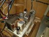
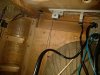
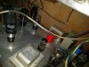
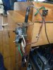
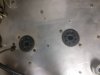
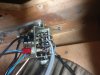
more picsIMG_20180511_002741.jpgIMG_20180511_002817.jpgIMG_20180511_002830.jpgIMG_20180511_021347.jpg

pics of the underside of the em34 magic eye, fm control and radiogram working...I will post some more pics when i take out the speaker/am pre etc.
 

Attachments

  • IMG_20180511_021354.jpg
    IMG_20180511_021354.jpg
    77.2 KB · Views: 2
  • IMG_20180511_021400.jpg
    IMG_20180511_021400.jpg
    68.8 KB · Views: 2
  • IMG_20180511_021418.jpg
    IMG_20180511_021418.jpg
    36.8 KB · Views: 2
The tuner appears a nicely manufactured sub-unit.
This tuner, FM.
index.php
 
Back
Top Bottom