• Please note that Audiokarma will be offline briefly for updates early on Monday morning, September 28th.

Video Tape Electrostatics - a follow-up

whsh93a

Super Member
Banned
I have finally finished my system (is a system EVER finished??).

You may remember that I made experimental electrostatic panels using plain old video tape.

I plan on posting plans in the near future for anyone interested.
(yes, I know - this thread is not as good without photos. I'll get some photos up when I get home)

Anyhow - I feel obligated to let everyone know just how amazing they turned out. I am actually flabbergasted at how mind-boggling good they are. Especially incredible is that they have few design errors. I know what I would do differently when I build replacement panels (which I will document for anyone interested) in case one fails in the future. But the errors are really minor.

Dispersion is excellent, too. They are completely adjustable in all axis. Each speaker uses a set of four seperate drivers.

I had relatives over on Thanksgiving and demonstrated them - I wanted to know if I was playing tricks on myself (that is, they must be good because I made them). But - apparently not - they were as astonished as I am. I didn't let them know what they were - I just began playing them. The comments were immediate. They were all in the line of "wow" and "Jeez!"

Their surprise was even greater when I removed the grill cloth to reveal the video tape speakers.

The cost for each speaker - even counting the special tools, oak wood, blown DVM meter (2KV was a little high), etc. etc. was amazingly low - something like $150.00 or so. The actual speaker elements are WAY cheaper. It's just mostly the stuff to make them look good that costs.

They are hanging on the wall and are about three inches deep and 36" by 18" rectangular. Now, my living room floor is clear and the sound is even better.

DH
 
Register to hide this ad
I'm really looking forward to your follow-up on this. The more detail, the better! I've toyed with the idea of building some stats for some time and would love to see how you did it.

David
 
Some photos

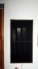
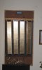
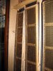
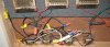
Here are some photos - quick and dirty...

Left to right:

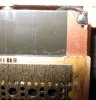
1- On wall, 2-Flash photo making grill translucent showing modules,3-Hangin modules, 4-Side view showing different pitch/yaw, 5- HV diaphram supply, (botom row)6-Close-up showing tape and gimble top, 7-Audio up-voltage transformers, 8-Close up of stators with tape diaphram behind, 9-Another close-up showing tape and HV connection.

DH
 

Attachments

  • Untitled 21.jpg
    Untitled 21.jpg
    177.9 KB · Views: 70
  • Untitled 23.jpg
    Untitled 23.jpg
    183.7 KB · Views: 70
  • Untitled 24.jpg
    Untitled 24.jpg
    191.5 KB · Views: 88
  • Untitled 25.jpg
    Untitled 25.jpg
    189.5 KB · Views: 65
  • Untitled 30.jpg
    Untitled 30.jpg
    146.3 KB · Views: 72
  • Untitled 31.jpg
    Untitled 31.jpg
    174.1 KB · Views: 54
  • Untitled 33.jpg
    Untitled 33.jpg
    170.2 KB · Views: 53
  • Untitled 35.jpg
    Untitled 35.jpg
    191.9 KB · Views: 51
  • Untitled 37.jpg
    Untitled 37.jpg
    179.9 KB · Views: 72
Full range?

Interesting stuff! I used to have a pair of Koss Model one full range electrostats. I also made a pair of electrostatic headphones (including drivers) about 30 years ago. I still have them.
I don't see any dynamic woofers in your photos. Are you feeding full range signals to your stat's? What kind of power are you applying to them? Where did you get the transformers and who made them? Are you getting 2KV out of that tiny blue supply? Any arcing problems? I hope you go into much more detail about your project in the near future. Congrats on tackling and evidently succeeding at an ambitious project.
2chanman
 
Last edited:
Very nice looking speakers. What size gap do you have between the stators and the diaphragm? Be very interested in more details on these, they sound like a great project.

David
 
Interesting stuff! I used to have a pair of Koss Model one full range electrostats. I also made a pair of electrostatic headphones (including drivers) about 30 years ago. I still have them.
I don't see any dynamic woofers in your photos. Are you feeding full range signals to your stat's? What kind of power are you applying to them? Where did you get the transformers and who made them? Are you getting 2KV out of that tiny blue supply? Any arcing problems? I hope you go into much more detail about your project in the near future. Congrats on tackling and evidently succeeding at an ambitious project.
2chanman

=========
Here are your answers:

I use a single 12" sub-woofer hidden away in the corner of the room out of sight. Crossover is at about 300 HZ using an active crossover between my pre-amp and the amps. The system is tri-amped. A Dyanaco ST-120 (60W) runs the sub and I use a pair of SWTP 207/A mono-block amps (60W) for the electrostats. I've tried all different types of amps/pre-amp combinations and this one sounds the best. I am planning to change the sub amp to a D-150 Crown in the future (to tighten the base). But the Crown puts out a pretty good thump when first turned on and I will need to add a time delay relay to it first.
The transformers are nothing more than standard 70V audio distribution types set up in series. That gets me the right voltage and also protects the transformers from potential over-voltage problems. I deemed it unnecessary to use the expensive full-range, high power, full frequency type since I never intended the statics to be full range. Cost for the transformers was about $3.00 each.
The 2KV is easy to make. I just used a standard CCFT supply and then built into it a voltage trippler on the output using a few HV rectifiers and disc capacitors. I also added a 40Meg HV resistor to protect the statics in case of arcing.
I can certainly drive them into arcing. But they get pretty loud before that happens. In the future, I will change the design slightly to increase the insulation level. It's one of the minor design flaws I encountered (I'm pretty surprised that I managed to avoid anything major on my first go-around with these!).
I will keep Karma posted.
DH
 
Very nice looking speakers. What size gap do you have between the stators and the diaphragm? Be very interested in more details on these, they sound like a great project.

David

The gap is about 1/4". Insulators are spruce strips from a hobby store. Generally work great. A single piece would work best as the insulation resistance at the butted corners is really just an air-gap - that is the point where arcing occures (when the speakers are cranked up).

DH
 
transformer configuration?

whsh93A:
I take it that you have the 4 transformer secondaries in series, using the joint between secondaries 2 and 3 as a center tap? Or is this NOT a push pull arrangement with 2 stators with the diaphragm between them? Did you parallel or series the 4 primaries? Do you have a low value(4 ohm) resistor in series with the primaries to keep the minimum impedance at a level the amplifiers can tolerate? Electrostatics are a capacitive load which most amplifiers don't like, as you probaly know. Just curious.
2chanman
 
Does anyone know if there is an on-line (or otherwise) reference that could help get me up to speed on the basics of this? This is over my head, but I feel like it's only a few inches over and I would really like to try this.
 
Does anyone know if there is an on-line (or otherwise) reference that could help get me up to speed on the basics of this? This is over my head, but I feel like it's only a few inches over and I would really like to try this.

Try DIY Audio. Check out their loudspeaker forum - there's an entire subforum devoted to building your own electrostatics and other planar speakers. Some really interesting threads, you can learn a lot there.

David
 
whsh93A:
I take it that you have the 4 transformer secondaries in series, using the joint between secondaries 2 and 3 as a center tap? Or is this NOT a push pull arrangement with 2 stators with the diaphragm between them? Did you parallel or series the 4 primaries? Do you have a low value(4 ohm) resistor in series with the primaries to keep the minimum impedance at a level the amplifiers can tolerate? Electrostatics are a capacitive load which most amplifiers don't like, as you probaly know. Just curious.
2chanman

=======
Yes - the transformers, including the resistor, are wired exactly as you suspect for my push-pull setup and the primaries are wired in parallel.

DH
 
Back
Top Bottom