• The move to the new server is done. There are some software and database maintenance updates in process. This has us passing the hat around to help out. We appreciate any donations. Seriously, even a dollar helps. The payment page may be found here - https://www.audiokarma.org/support.html

Vintage European Capacitor Values - How to read them

Dig22

Active Member
Hi,
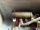
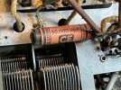
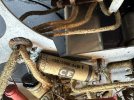
I'm working on a friend's French radio and want to make sure I'm reading the values correctly.
They use commas or decimal points in some values.

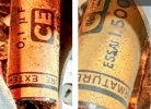
Is 20.000 uuf 1.500 VCC = 20K 1.5V? Please correct me.

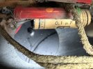
I'm completely thrown by the 100/1000 marking.

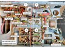
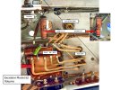
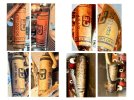
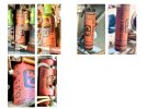
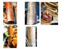
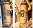
I've attached a few photos to illustrate.

Thanks for your help.IMG_1830.JPGIMG_1831.JPGIMG_1833.JPGIMG_1836.JPGIMG_1839.JPGIMG_1841.JPG
 
Register to hide this ad
uuf=nf

vcc= voltage coefficient of capacitance but i am not sure that they are using the designation like that. i'd think it was just the voltage but i'm unsure.

better off to just hang tight until someone like @gadget73 pops in.
 
uuf = pf. Micro-microfarads. I didn't think the Euros used that one, I've only ever seen it on old US stuff.

Not entirely sure on what VCC stands for but its definitely some sort of voltage number. I'd think that to be a 1500 volt part.

100/1000 I'm betting is 100 picofarad at 1000 volts.


How old is this thing? Looks like the same sort of resistors US radios used in the 1930s, and the paper caps are similar looking but with different marking terminology. I've never been into a French radio or anything pre-war from Europe.
 
Being a foreign ( European) item, might try elektrotanya.com for a schematic &/or parts list. Good luck!
 
Hi,
I'm working on a friend's French radio and want to make sure I'm reading the values correctly.
They use commas or decimal points in some values.

Is 20.000 uuf 1.500 VCC = 20K 1.5V? Please correct me.

I'm completely thrown by the 100/1000 marking.

I've attached a few photos to illustrate.

Thanks for your help.View attachment 3178094View attachment 3178095View attachment 3178097View attachment 3178098View attachment 3178099View attachment 3178101
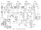
Here are some more photos. I'm still trying to figure it out.
 

Attachments

  • Slide1.jpeg
    Slide1.jpeg
    191.8 KB · Views: 24
  • Slide2.jpeg
    Slide2.jpeg
    147.1 KB · Views: 19
  • Slide3.jpeg
    Slide3.jpeg
    158.3 KB · Views: 18
  • Slide4.jpeg
    Slide4.jpeg
    116.9 KB · Views: 16
  • Slide5.jpeg
    Slide5.jpeg
    108.2 KB · Views: 20
  • Schéma.png
    Schéma.png
    242.8 KB · Views: 23
whole numbers of microfarads are pretty much guaranteed to be an electrolytic cap.

Nanofarads are a newer thing, but 1nf = 1000 picofarads or 1000 uuf so 20,000 uuf = 20 nf. Probably C10 or C12.

honestly the voltages on most of those paper caps seem higher than I'd expect them to be. The only cap in here that I'd expect to be a high voltage one is C16. Everything else I'd have expected to be rated for maybe 500 volts. I normally stock 630 volt parts.
 
whole numbers of microfarads are pretty much guaranteed to be an electrolytic cap.

Nanofarads are a newer thing, but 1nf = 1000 picofarads or 1000 uuf so 20,000 uuf = 20 nf. Probably C10 or C12.

honestly the voltages on most of those paper caps seem higher than I'd expect them to be. The only cap in here that I'd expect to be a high voltage one is C16. Everything else I'd have expected to be rated for maybe 500 volts. I normally stock 630 volt parts.
Thanks Gadget. But I'm still confused on a few of the markings and C16.
1. C16 - how many volts would expect and what type of capacitor?
2. the use of 0,#... are 0,1 and 0,25... 1 and 25? Or .1 and .25? And is the 0,25 uF or uuF? I can't read the marking.
3. the 100/1000 750 VCC.... is it 1/10 or .1? or what is it? And would a 630V cap be a good choice?
4. Lastly, C5, the cap can...the schematic shows only 1 16mF, but the can shows 16+16. Because the markings are different on the other caps, i'm double checking everything.

Thanks again
.100:1000.png
 

Attachments

  • 0,1.png
    0,1.png
    278.1 KB · Views: 2
  • 0,25.png
    0,25.png
    288.2 KB · Views: 2
Last edited:
I'd read that as 100 picofarads at 1000 volts just based on the markings. Not sure what number that is on the schematic, looks like possibly Ca, but its next to R11.
 
I'd read that as 100 picofarads at 1000 volts just based on the markings. Not sure what number that is on the schematic, looks like possibly Ca, but its next to R11.
It has 750 VCC on it in the photo. Would a 630v work here? The schematic shows no + marking for the Ca. But if a capacitor has a black band on one end and no + on the other end, its not polarized… do I have that right?
 
The bands are outside foil.

The most properly correct answer is you dont go down in voltage from the original. Reality is that its not likely to get anywhere near 630v. Looks like the filter cap is 500v, so it won't be past that.
 
Thank you all for helping me get my Model 52 up and running. I struggled with relentless humming which turned out to be overhead lights, especially LEDs on a dimmer. Is there any fix? I've never experience any audio gear so sensitive to other electrical devices.

Thanks again.

Dig22

SNR Model 52.png
 
Thank you all for helping me get my Model 52 up and running. I struggled with relentless humming which turned out to be overhead lights, especially LEDs on a dimmer. Is there any fix? I've never experience any audio gear so sensitive to other electrical devices.

Thanks again.

Dig22

View attachment 3241103
I think if you connect it to a decent UPS you should get rid of electrical interference in the power-line. But if it is due to electromagnetic radiation, then you could build a faraday cage around it, or at least the top, back, and sides.
 
Last edited:
I think if you connect it to a decent UPS you should get rid of electrical interference in the power-line. But if it is due to electromagnetic radiation, then you could build a faraday cage around it, or at least the top, back, and sides.
Or turn off the offending lights & enjoy the dial lights glow.;)
 
Back
Top Bottom