• The move to the new server is done. There are some software and database maintenance updates in process. This has us passing the hat around to help out. We appreciate any donations. Seriously, even a dollar helps. The payment page may be found here - https://www.audiokarma.org/support.html

Vintage Fisher speaker ID ?

Techforce

Member
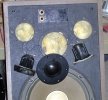
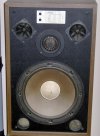
Cannot locate a model number on these -
Picked em up on the curb yrs ago, no grills on them and the pressboard cabinet may have had water damage
as some parts are broken and breaking off. Maybe I can use plastic wood to square that off, then paint them as
a project sometime, but right off it seems at least 1 mid range is open, they are Philips MR525 5 In dome mid range
like shown here


Any ideas on what would be good replacements for them?

Not sure if the Tweeter horns are good yet.

The woofers appear to be 12 in types and are marked SC-80664-1 (4 ohm)
one seems ok, I think the other is ok too.

Any idea the Fisher model number on these, and what would be some ideas for making new covers?
 

Attachments

  • HPIM1525.JPG
    HPIM1525.JPG
    117 KB · Views: 70
Register to hide this ad
Swechsler is spot on. None of those drivers are Fisher originals. That dome mid is from Phillips. And like the peizos, they were never used is Fisher speakers. In fact, I don't recall Fisher ever using dome mids, period.
 
Still unable to find the Fisher model, so I set about getting new mid's, they are Dayton aluminum, but the one I installed it into they are not playing.
I took the horns out and they measure open, so will need to replace them too with something. Any ideas?

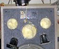
I removed the response chart label, and there are threaded nuts I am taking out on the 2 controls, so I am guessing that will let me pull out the board
or whatever is behind there for an inspection.

One mid wire has a resistor with a cap in series....not sure if thats suppose to go to the plus or the minus of the mid? The terminals are not marked red or black but one is larger.
 

Attachments

  • HPIM1573.JPG
    HPIM1573.JPG
    228.5 KB · Views: 10
Piezo horns cannot be checked with an ohmmeter, as they are a capacitive load. You can test them by connecting them directly to a speaker wire from the amp. They are actually pretty difficult to blow. But my advice would be to replace them with a dynamic tweeter anyway. Alternatively, you can put a 4Ω resistor in parallel with each one, which will make the crossover operate more or less correctly. That's assuming the original tweeters were 4Ω and connected in series.

I would have kept the Philips mids, as they are probably the best of the components that were used.
 
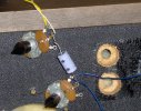
Here is another pic with the controls out. They are 20 ohm pots. Cap is 4.7 uF / 70V. It seems like it may be open, will have to check.
 

Attachments

  • HPIM1574.JPG
    HPIM1574.JPG
    211.9 KB · Views: 5
Cap checks good at 5.56 uF, I shot the potentiometers with contact clean anyhow and they read good. The resistor in line with the mid
is 4.7 ohms, checks good.

Looks like the (2) outer black wires to each side of the piezo head directly to the spkr terminal. If Indeed they are capacitive maybe thats
why nothing is getting to the mid? Then the 4 ohm resistor idea may be what is needed?
 
Looks like the (2) outer black wires to each side of the piezo head directly to the spkr terminal. If Indeed they are capacitive maybe thats
why nothing is getting to the mid? Then the 4 ohm resistor idea may be what is needed?
Whoever modded these at least knew that a piezo doesn't use a normal crossover. To use the resistor idea you'll need to connect them to the tweeter output of the crossover, assuming it hasn't been removed. They (the tweeters) should be connected in series. Or, you can connect the tweeters in parallel, along with an 8Ω resistor in parallel with both. This actually makes more sense, now that I think about it; I'm assuming that the crossover doesn't have a separate output for each tweeter (it probably doesn't).

I don't know if that's why you're not getting output to the mids, but I suspect it's more involved than that.
 
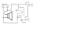
The tweeters appear to be in series on the outside connections with the crossover / mid in between them. I will try to draw a schematic.
My thought is that since the signal is places on the end terminals of the horns, with the rest of the stuff in between, there is no way for it
to reach the stuff in between because they are basically capacitive , so you have a lot of reactance preventing function.
 
I tacked in (2) 2.2 ohm 0.5W resistors in series and put them accross the piezo terminals thinking that would at least get sound to the
crossover / potentiometer setup with the mid running off it, but the only one with sound coming out is the driver still.
 
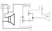
Heres a schematic I hand drew, plus a photo of the potentiometers. The blue wires are the ends of the tweeters,
the top pot is the mid control and the yellow and white wires from it go to the mid. I didnt drw in the 4 ohm resistors I tacked
on in parallel with the tweeters, but either way it didnt matter.
 

Attachments

  • Fisher_wiring.jpg
    Fisher_wiring.jpg
    34.6 KB · Views: 6
  • HPIM1577.JPG
    HPIM1577.JPG
    198.2 KB · Views: 7
I redrew the schematic based on my thinking on how it should be as the mid was never gonna work with only one connection to it.
Now the mid should work as its right on the main terminals thru the 20 ohm control...and that
control now feeds the piezos so depending on how much the mid sees,
the tweeters are effected by that level and they also have a 20 ohm control.

I dont know if the 4.7 uF / 70v
cap is better off in between the 2 piezos or
where I put it. Not sure if I should keep the 4 ohm resistors accross the piezos.
 

Attachments

  • Fisher_wiring_rev.jpg
    Fisher_wiring_rev.jpg
    25.1 KB · Views: 3
Your diagram doesn't show any resistor across the piezos. As I noted earlier, I'd connect them in parallel with one 8Ω resistor (or 2 4Ω in series) across their terminals.
 
I just tried that, but its still in the config as the first diagram and makes no difference....will try and rewire it to my new diagram,
only the bottom terminal of the woofer will go to the wiper of the pot and not the end terminal. I am figuring that way the horns will be dependent on how much
the mid is driven for their signal. Dont know much about crossovers, but I think some of them use a small coil but that may be to feed non peizo tweeters.
 
All the drivers should be independent of one another (i.e. don't wire the tweeters to the output of the midrange pot). Work on one section first; maybe try to figure out the problem with the woofer while all other drivers are disconnected. In a 1st order crossover, which these appear to use, a single capacitor in series with a driver will act as a high-pass filter; a single coil (usually referred to as an inductor or choke) in series acts as a low-pass filter. More complex crossovers use a combination of series and parallel connections. At a minimum, to protect them from low frequencies that can burn them out, midrange and tweeter should have a capacitor. This (protection) doesn't apply to piezos but you still want the cap and resistors to improve the sound.
 
Back
Top Bottom