Hi everyone,
I'm working on a vintage Pioneer DT-500 Audio Digital Timer and hitting some perplexing display issues. I believe it's an NE model (220V 50Hz, no external voltage/frequency switches). This unit was not used and not connected to electricity for over 20 years before I recently powered it up.
The Display Problem (with examples): The VFD display shows specific, consistent errors for certain digits, but it's a bit complex:
Given the complex, digit-specific nature of the errors (not just a stuck segment, but incorrect additional segments for certain numbers), especially after long storage, my main suspect is the Q1 MN6076 AC Clock Timer LSI chip. It feels like its internal logic for decoding and driving the display segments has become corrupted or has degraded with age.
What I'm Looking For:
I'm working on a vintage Pioneer DT-500 Audio Digital Timer and hitting some perplexing display issues. I believe it's an NE model (220V 50Hz, no external voltage/frequency switches). This unit was not used and not connected to electricity for over 20 years before I recently powered it up.
The Display Problem (with examples): The VFD display shows specific, consistent errors for certain digits, but it's a bit complex:
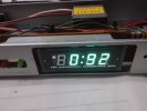
- A "3" in the tens-of-minutes position displays as a "9" (e.g., 0:32 shows as 0:92). The "0" and the "2" in this example are correct.
- A "2" in the tens-of-minutes position often displays as an "8" (meaning an extra 'f' segment, top-left, is lit).
- A "1" in the hours position (e.g., 1 o'clock) often displays with an extra 'e' segment (bottom-left) lit.
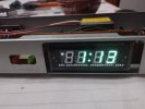
- For example, a time like 1:23 will display looking like "1+e : 8 9".
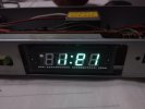
- Interestingly, not all instances of a digit are necessarily bad all the time, or it depends on the other digits displayed (e.g., the user manual implies that sometimes "1"s can be okay, but the "1:21" example showed errors too).
- It seems all individual display segments can light up correctly as part of other, correctly displayed numbers, suggesting the VFD tube itself might be okay. (I have photos of these display errors I can share in the comments, e.g., "0:92" and what "1:23" looks like.)
Given the complex, digit-specific nature of the errors (not just a stuck segment, but incorrect additional segments for certain numbers), especially after long storage, my main suspect is the Q1 MN6076 AC Clock Timer LSI chip. It feels like its internal logic for decoding and driving the display segments has become corrupted or has degraded with age.
What I'm Looking For:
- Does this pattern of errors (specific digits being augmented by extra segments) strongly point to the MN6076 LSI chip, especially after long-term storage?
- Any advice on what part of the circuit that diode/capacitor connection might be in, if it were a fault, that could lead to these symptoms? (I'm still trying to precisely identify them on the schematic).
- Experiences sourcing a replacement MN6076?
- Any other tests or things to check on the board before considering an IC replacement? I have a soldering iron and a multimeter.