• The move to the new server is done. There are some software and database maintenance updates in process. This has us passing the hat around to help out. We appreciate any donations. Seriously, even a dollar helps. The payment page may be found here - https://www.audiokarma.org/support.html

Vintage solid state repair, Winston 560

stronk skonk

New Member
Hello all,

I recently picked up a low wattage (speaker is rated for 2 watts) amp on the verb, and it has a few issues. I think it needs a cap job, because after a few minutes of playing on higher volumes (so far higher volumes only) it starts humming and ring modulating. At low volumes it works just fine. I ordered some new caps and plan to swap them out though.

However, i had a few more questions maybe some people could help with. The amp doesnt seem to have a fuse, rather, it has a two-prong plug with one lead going into the volume knob which acts as an on switch, and the other lead going into the pst and coming back out and going into the switch as well.

Are there generally fuses in these older switches? Should I plan on upgrading it to have a fuse if not? Also, if i wanted to install a 3-prong plug would i need to find a new transformer? It only has 2 leads. My uneducated guess is that it wouldn't be a very good idea (or even possible) to try to affix a new plug into the pst since one of the leads is winding into the transformer.

I'd be happy to upload pictures of the circuit later. Unfortunately, there doesnt seem to be any schematics on the internet, although I could search a little harder. I'm breaking into repair as a hobby and i'd like to understand as much as possible before i even plug this thing in to work on it.

I'd appreciate any help, thanks!
 
Register to hide this ad
Interesting little piece of gear.

It seems to have been introduced as a vacuum tube unit(maybe even a kit), and made a transition to solid state during what would appear to be fairly limited production.

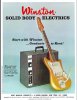
Note the slick sheet in the 'verb ad says it has 3 tubes, and there's no solid state badge on the face.

Appears the tube model also had a tone control.

winston amp.jpg
 
Last edited:
ring modulating

Welcome to AK, and congratulations on being (I'm guessing) the first person to ever use this term in describing a problem.

I'm pretty much only a home hi-fi guy, so pardon me if this is a naive question, but are you sure it isn't acoustic feedback that happens at higher volumes? You could rule that out by seeing whether it still happens with an all-electronic instrument like a keyboard, or when using something like a home hi-fi source of input.

About the fuse questions, I can say that I've never seen a fuse inside a switch. I have seen fuses (usually thermal fuses) built into power transformers, but I don't think I've ever seen it in gear of this age. If you wanted to install a fuse, you could splice an "inline fuse holder" into one of the leads of the power cord. You could start with maybe a 1A fuse, and see if you can play as loud as you wish without blowing it.

I think I'll leave it for someone else to opine about changing to a three-prong plug & cord set. You might want to say whether the present two-prong plug is a polarized one (where one of the prongs is wider than the other).

Oh - you might also want to confirm (or not) whether "pst" refers to the power transformer - it's not an acronym I'm familiar with.
 
I don't usually sweat it when someone doesn't re-engage, but I'm bummed this time. I would have really liked to hear more about the ring modulation symptom, which seems unique. And the OP almost has to be a musician - other than maybe Dilbert, who else would use that term? - so it seems likely that it is a carefully chosen and precise description. I have to say that such precision is not exactly the norm, on AK or anywhere.

But then again, it's not like I have the first vestige of a clue about what the cause of that symptom might be. Re-capping is probably a decent approach.

Anyway, here's an attempt to page @stronk skonk, just in case. (And just in case I got the spelling right. Are spaces allowed in pages? I guess I'll find out in a minute.)
 
Last edited:
sorry for the delayed response. I wanted to reply after switching the caps out but i haven't been able to yet. really appreciate your help though.

I tried it with a synth and let a sine wave run through for a while and it had the same result. Hum kicks in after about 5-10 minutes. Oddly enough, i plugged in a 1/4 patch cable with nothing attatched and the hum didnt occur (even at full power for ~30 minutes). I'm gonna upload a youtube vid and link it here later so you can hear (will also have guitar). If you'll notice, turning it off for a few seconds makes it stop, even though it comes back after a few seconds. Having it off for a few minutes seems to make it go away. This seems to me (again completely clueless) like a cap discharging. Also, the hum seems to be exactly 120 Hz.

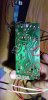
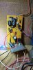
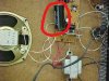
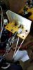
Hopefully these image links work, you'll notice that my circuit seems to have a capacitor that is MUCH smaller than another seen in a listing for a different model 560 online. The red circles on the pcb look somewhat burnt to me, and im getting a feeling that a bad cap job might be the culprit here. If you look closely, its been sloppily replaced with what seems like a leg cut from another cap to make it reach between joints.

Also please forgive my poor terminology. I've seen PST used to refer to 'power supply transformer,' and ring-modulating might not be the most clinical term either, but it does sound like some sort of frequency modulation is occuring to me. I am a musician, definitely not a Dilbert! haha


pKaFqNk

q2gnV17


fPlxJTL
 
Last edited:
pcbside.jpg components.jpg Iotherwinston_LI.jpg


just by looking, can anyone say if im going to need to get a different cap? do larger caps have different properties that i should be concerned about since the replacements i ordered are roughly the same size as the one currently installed. I cant really make out the values on the different one in the image but it looks to be the same (1000uF 25V).
 
Last edited:
The red circles on the pcb look somewhat burnt to me, and im getting a feeling that a bad cap job might be the culprit here. If you look closely, its been sloppily replaced with what seems like a leg cut from another cap to make it reach between joints.

Agree that it's not the neatest job, but my guess is that the burnt-looking areas are just residue from rosin-core solder. If that is so, it will clean off with a medium-strength solvent. You could try rubbing alcohol to start. If it's just rosin, it's not really a problem.

I wouldn't worry much about physical size of capacitors. Contemporary caps are much smaller than ones used in the 60s.

This is a seriously wild guess, but I think it could be that the underlying problem is what's called "thermal runaway". The output transistors heat up, and heating up makes them conduct more current, which causes more heating, and so on. If you could very carefully measure the voltage across one of those large resistors (the ones with brown-black-gold-silver stripes), you could check my guess. If I'm on the right track, there will be very little voltage developed across the resistors - maybe a few millivolts - when the amp is first turned on from cold, but when the amp gets to the point of humming, the voltage will be higher. (Edit: If you do this test, do it with the amp silent - either no input, or volume turned all the way down.)

Also, if it's a runaway situation, that metal plate (which I'm assuming is where the output transistors are mounted) will get pretty hot. That might be the most practical check of my guess.

What to do about runaway, if that is really the problem, is tricky. More wild guesses about that later, if it still seems relevant.
 
Last edited:
Just checked, after turning on voltage rose about ~40-80 mV and when the hum kicked in it shot up to about 1.3 volts. The plate was fairly hot and even the clamps i had on the resistors were getting pretty warm.

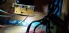
Here's a shot of the transistors i forgot to include. Anyways ideas where to go from here? Wish i had a good hand at drawing circuits. Itd probably help.
 

Attachments

  • 20230414_154817.jpg
    20230414_154817.jpg
    73.9 KB · Views: 10
Last edited:
Anyways ideas where to go from here?

OK, I'm pretty convinced that it's a runaway situation, but there's no basis to theorize whether the fault is with the thermistor (the black disk-shaped part between the two transistors or with the transistors themselves. What I might do, if this was on my workbench, is to replace the transistors (since for sure they have had a hard life), and if that isn't successful, then try to figure out a replacement for the thermistor. In any case, all these parts should be pretty closely situated onto that metal plate. They all need to "feel" the same temperature. I wonder if some clamps for the traansistors hve gone missing.

Of course, it's not like finding replacements for any of the above is going to be easy. Can you see ID numbers on the transistors? They've almost sure to be Germanium parts, but I'm having a hard time figuring whether they could both be the same. From what I can surmise from the pictures (in particular, the absence of any transformers other than the PTS), the two transistors should be complementary - one of them should be what's called an NPN, and the other a PNP - but I don't think complementary parts of that sort existed at that time.

However this epic proceeds, I would really like to know the IDs of those two transistors.

HTH
 
I was actually going to ask what the thermistor was, thanks for clearing that up. Here's a close up of it, and it definitely looks like its seen better days. It looks like the transistors are in casings and i can kind of see ink underneath so hopefully their markings are still intact. Im going to wait until the weekend to get a few more tools to unsolder the leads so reaching the transistors is easier to work with.

Also regarding identifying the thermistor, would identifying the transistors make it easier to find out what value part to replace it with? I did a quick search and saw people making graphs of resistance vs temp and im not sure i have the necessary tools to measure that (temp at least) at the moment.

In the mean time thanks again. Really appreciate these detailed responses.

Edit: could you elaborate on the missing transistor clamps? Never seen or heard of such a thing
 

Attachments

  • 20230427_165007.jpg
    20230427_165007.jpg
    64.4 KB · Views: 11
Last edited:
transistor clamps?

First I'll cut to the chase - I no longer suspect that anything is missing.

Transistors in the output stage of audio amps are typically very tightly attached to some metal structure that serves as a heat sink. That's what I clumsily tried to convey by "clamps". Your amp's transistors are fitted into sleeves that are in turn attached to the heat sink. Presumably this setup worked well enough when the amp was new.

IDing the thermistor is probably going to be hard. If it comes to thinking about replacement, it would be really, really good if there was a schematic available. At least, with that, we could guess at whether we want the thermistor to have a higher or lower resistance.

Still very curious about the transistors IDs. I hope their markings will be legible when you have some time to get them out of the sleeves.
 
Last edited:
Nevermind! Here they are.
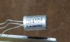
One looks to be a amperex 2N4106 with a red E stamped on top and the other (hard to read not pictured) i think a 2N4105 with a blue G (possibly 6) on top. A quick search seems to show they are pnp and npn respectively.

Either way im going to order a new pair right now. As for the thermistor however, there doesnt seem to be any schematics readily available. I found an article on calculating the beta value by submerging it in water at known temps and substituting values into an equation. Does this seem like a relevant approach?
 

Attachments

  • 20230427_231305.jpg
    20230427_231305.jpg
    58.5 KB · Views: 11
  • 20230427_231449.jpg
    20230427_231449.jpg
    62.6 KB · Views: 11
Might not be able to post any more until next week. (Not that I've been of much real help so far.)

So they really are complementary germanium transistors! I'm not sure I've ever encountered such. That means the thermistor is probably just connected between the base leads of the two transistors. The base leads are the middle ones. Can you confirm that this is how things are connected?
 
Yes you are correct, it's connecting the middle terminals.
Also no worries, its gonna take a while for the new ones to show up anyways. Have a great weekend and such.
 
I found an article on calculating the beta value by submerging it in water at known temps and substituting values into an equation.

Turns out I find myself with time to post today. Probably too much time!

So, now that you discovered more about the transistors, we can safely assume that the present thermistor is a type called NTC (Negative Temperature Coefficient). If it turns out that replacing the transistors doesn't cure the problem, then suspicion falls on the thermistor. The approach you describe would work, but keep in mind that, if the thermistor is our prime suspect, it might be that its temperature coefficient is too small. So what you'd be aiming at in a replacement is a thermistor that has about the same resistance as the present (since the amp apparently works OK until it heats up), but which has a larger (more negative) temperature coefficient.

How much larger a coefficient? That's probably guesswork. To be conservative, go for as large (most negative) coefficient you can find. If the amp then works fine from turn-on all the way up to full tilt boogie, you're golden. The worst case would be if the amp starts to sound unpleasant (but without the humming) when it heats up. That would be a sign that a thermistor with a smaller (less negative) coefficient is needed, but no harm will have been done.
 
So! the last transistor i need should be arriving in the mail today. Hopefully i can get them soldered in neatly and this resolves the issue. However, for the sake of potentially getting ahead if the thermistor is the issue:

The resistance reads about 25 ohms when the amp is off, when i turn it on the resistance jumps up to about 60. Is this normal? I dont understand why this happens, especially since it seems to be a NTC for sure. The components start to heat up immediately and resistance starts to drop, but the jump up is confusing to me. Is it some kind of function of incoming current being limited?

Anyways, if the transistors arent the issue im gonna pull the thermistor out and do some calculations and try to troubleshoot from there. I've already ordered some 100 ohm NTCs with a high beta value (~4500K), would the increased resistance rating damage the transistors some how? I wont attempt to swap them out until i know the values of the current one, but im generally curious how changing the resistance value would affect things. If i shouldnt change it, should i look for a ~25 ohm or a 60 ohm?

Hope you (and anyone else reading this) have been well. Thanks again!
 
when i turn it on the resistance jumps up to about 60. Is this normal?

Generally it's not valid to measure resistance in a powered-up circuit. When you power up, the thermistor will have some voltage across it, which is likely to confuse the meter. (There is also a risk of damaging the meter in the general case, though probably not in this case.)

The most reliable way to measure the thermistor's resistance would be to disconnect at least one of its leads from the rest of the circuit.

If a replacement thermistor has a higher "cold" resistance, it will cause the transistors to conduct more current. Whether it would be too much more, I can't say.
 
New transistors in. Almost had me fooled, it was working perfectly and the same short happened except this time the sound cut out totally. Not even the hum. Odd? I'll check a few more times to see if this is consistent.

For what its worth, the beta value on the thermistor seems around ~2900, and while it was removed from the board it measured about 50 ohms around 25 C. Im gonna order some replacements tonight, but of note right after turning it off the 2n4105 was the only thing that really felt hot on the board.

Im gonna recheck my solder work, but there will probably be an update on the thermistor change soon.

Edit: it cut out with the hum again but after a while longer than usual. The input didnt die out but it was more mangled than it was before the swap.
 
Last edited:
2n4105 was the only thing that really felt hot

If only one of the two heat-sink-mounted transistors is getting hot, that runs counter to my idea that it's "just" thermal runaway.

Edit for a massive brain cramp, in which I suggested checking for DC across the speaker. The speaker has to be cap-coupled, and I don't think it's very likely that the coupling cap starts to "leak" DC only after the amp has been playing a while. I suppose it's not impossible, though, so maybe the check makes sense after all. But only because I'm stumped for other ideas :(.
 
Last edited:
Just saw this after checking. First off there is no dc before or after hum kicks in, so im assuming this is good news.

Secondly the heat sink plate was hot just after hum/unplugging, i was probably just jumping to conclusions (i.e. was wrong about the 4105 being the only hot component). For now im going to (optimistically) assume it was insignificantly warmer than anything else, because, again, everything seemed to be uniformly hot upon shutdown. Sorry for eliciting any undue brain cramps. This is an uneducated guess, but the hfe on the 4105 is way smaller than the 4106, maybe due to its design/function it might be heating up faster?

Anyways, I ordered two new ntcs from mouser last night, both 50 ohms with a 3200k and 3400k beta. Im gonna start with the 3400 and hopefully we get good results. Until then!
 
Back
Top Bottom