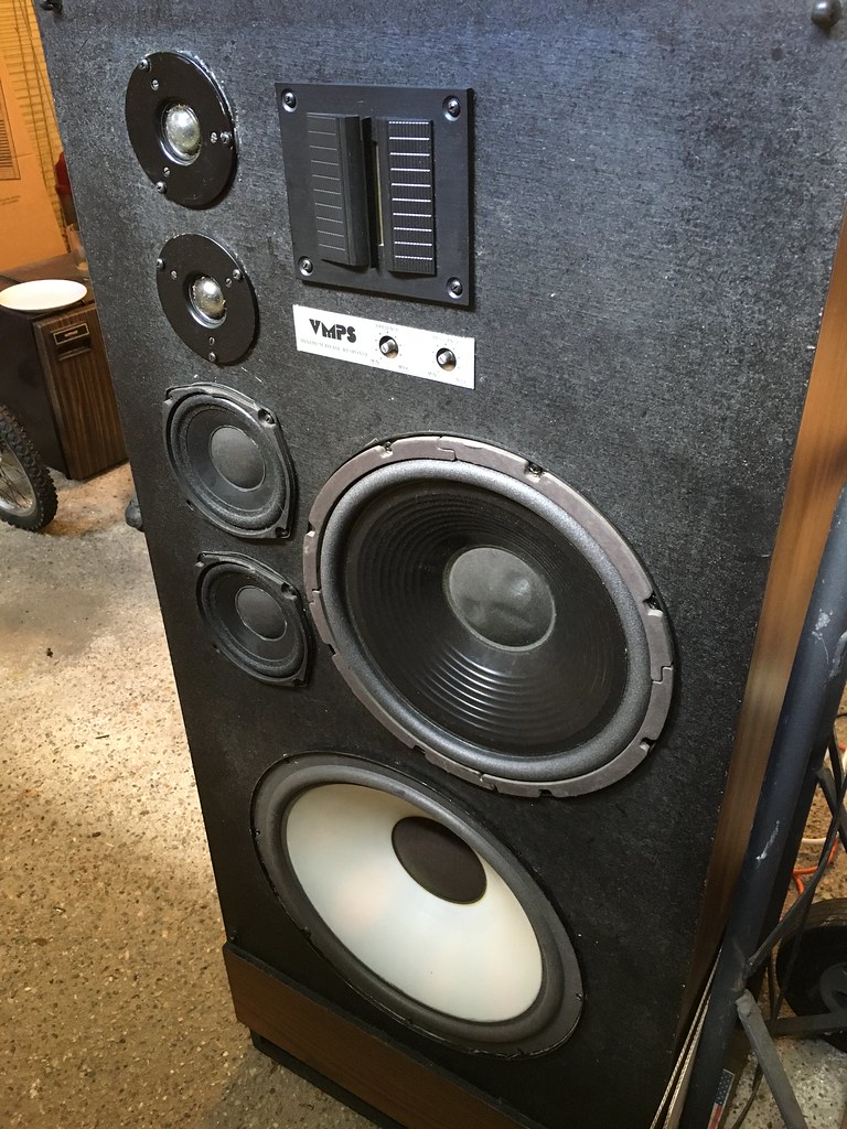
OK, here's the run down. I want to start with the punch line: I got these $#@kers working!!!
Man, they sounded terrible when I got them. It's a whole new enchilada now. DEEP, rumbling bass, crystal clear midrange. The highs are not quite as sharp as I would like them, or as I would expect from a pair of Morel MDT28s, but the balance is there.
I equate the sound to a cross between a JBL monitor and an old AR2ax or AR3. I actually just had a finished VMPS next to an AR2ax in the shop and the voicing and timbre were very close. The difference being, the VMPS can play
LOUD AND HARD.
So, let me take you on a journey.
First, audiocircle.com has been a fantastic resource for these speakers. There's a VMPS sub forum and although VMPS is no longer in business, Brian's son is on the site semi-frequently and posts interesting resources for people to download and use for restoration work. Also, many many thanks to member ST86 (Ed from Mass) for his help in getting everything sorted out.
Next, a brief history lesson. VMPS = Veritone Minimum Phase Speakers and was started by Brian Cheney in 1977. The SuperTower/R was introduced in 1982 as a more approachable version of the immense SuperTowerII speakers. The "R" represents the ribbon tweeter used in this design which was then carried through generations of designs until Brian's passing in 2012 and the subsequent closure of the company. Wikipedia has a lot more on the history, but that's a briefing.
There are a few design notes to consider when looking at these speakers.
- The speakers were designed with a "quasi-second order" crossover network. Brian didn't want necessary phase shifts in his crossover, which are typical of Butterworth or Linkwitz-Riley networks used in 90% of all commercially built speakers. Brian employed a series crossover, similar to those used by Sonus Faber and Fritz Speakers, where a minimal number of components, and further a minimal number of resistors and capacitors, are used to crossover a number of different drivers. SO, when reading the schematic, throw away everything you thought you knew about crossovers.
- Because of the above crossover design, changing the circuit impedance by adding or removing resistance in key places, will affect crossover points. This was my biggest stumbling block coming into these speakers. I experienced disgusting muddiness in the mid-bass frequencies and attributed that to a faulty crossover design. What I didn't realize was the PO had forgotten a key component to the crossover network that balanced the whole system. In this case, a 25 ohm resistor is mounted in series with the 12" mid-bass coupler. The mid-bass coupler is then wired in parallel to the 15" bass driver, and both of those drivers are wired in series/parallel to a pair of midranges. In layman's terms, without that 25 ohm resistor, too much energy was going to the 12" driver, causing a huge imbalance in the system. Cool stuff indeed!
- Bass Management was one of VMPS's calling cards. Brian used passive radiators in very creative and complex ways to managed bass. In this case, a 15" passive radiator is slot-loaded at the bottom of the cabinet. The PR is a very lightweight paper cone with a very compliant suspension. The PR uses about 6 ounces of ballast to tune its resonant frequency to just under 22Hz, and the slot causes any unwanted mid-bass frequencies to be acoustically filtered at a very gradual 6 dB rolloff. It's rather genius actually. At first I thought it was similar to the down firing woofer in the Snell A or AR9LSi, but its not. It's a passive component that is tuned specifically to enhance the last 2 octaves of the bass region, without sapping any power from the circuit, or causing any unwanted coloration. When I got these speakers, the PRs were a mess. But I weighed the putty that was used as ballast and will tune them back again using my mic and REW software to get that bass energy concentrated in the 20 Hz range.
- The system is technically a 5-way, but the literature calls it a 6-way due to the nature of the PR, as described above. Yet for all this, the crossover uses 9 components (not including the drivers themselves). Heck, my Cionnsaile Monitor uses 9 components in the crossover and it's a 2-way!!!
OK, so on to the pictures.
Here's a pic of the PRs out of the cabinet. The putty was used for tuning. One was missing all the putty, the other had it falling off. A complete mess. The next iteration will be much different.
Here's a shot inside the cabinet. The white stuff is a ceramic paint called "Soundcoat" which was offered as an option to dampen the cabinet from resonances. As you can see, there's not much bracing inside and the walls are 7/8" particleboard.
Also note the wiring. Another option was the addition of Monster Low-Loss Hi-Guage cable for the low frequency drivers. This stuff is basically like battery cable but very flexible. It's a bitch to solder and the PO made an absolute mess of the soldering on this speaker. I cleaned things up a bit as I went along. For the high range drivers, a solid stranded OF silver wired was used.
One more thing to note, the PO had removed all acoustic stuffing from the enclosure. Usually a PR'd speaker has some acoustic fill, mostly to filter unwanted midrange resonance/ringing. But this design actually required that the cabinet be filled almost completely with fill. The reason for this is that the Mid-bass coupler and the bass driver share the same cabinet volume. And the cabinet is huge like a monkey coffin, or even a people coffin. The design is called "aperiodic" in the literature. I think this is because the acoustic fill slows down the back wave of each driver so as to not have them reflect unwanted frequency modulations on each other. Then the bottom of the cavity is left without fill, to allow the PR to "breathe." Adjusting the acoustic fill quantity and location is part of the bass tuning exercise.
At the top of the cabinet is a piezo tweeter used for "ambience enhancement". It's part of the same circuit as the Morels, but is padded with 3.75 ohm across it.
Here's a peek at one of the crossovers. This is for the LF drivers. One thing that ST86 noticed was that the wiring was reversed. The red wire was soldered to the black terminal. Hence the two woofers were running out of phase with the rest of the circuit for goodness knows how long! This occurred only in one cabinet. The other speaker had all drivers correctly in phase. One might wonder, WHY? Well, the drivers, although having identical model numbers, have their terminal locations switched. In other words, on one 12" driver the (+) lead is on the right and on the other the (+) lead is on the left. I think the PO just got confused and assumed that the markings were the same for both.
This is highly unusual. Especially for speakers that are in sequence. #s 9049 and 9050. More on that later.
A picture of the HF crossover. All components were removed from the circuit and tested. Everything was well within spec. Mid caps measured 5.53 and 5.54, respectively; tweeter caps measure 1.52 and 1.52; and super tweeter "Wondercaps" are running .89 and .88.
Note, these values differ from those in the schematic I am about to post. Why? Well, remember this product line ran for a number of years before being dropped. Somewhere along the line Brian stopped sourcing parts from Morel and Gefco and started sourcing parts from Misco and Focal. That's why the system Botrytis posted looks different. It is. The crossover design was changed in later models, so the values will differ, in some cases they differ A LOT and the crossover frequencies stay largely the same. >>>Remember what I said about throwing away your crossover knowledge for this one?
Here's a shot of the filthy soldering job I started with.
A shot of the HF drivers. Dual Morel MDT28s and a Philips ribbon tweeter with a 0.35 mH inductor in parallel. I should note, this ribbon according to the PO was replaced and "upgraded" some years back. It's slightly larger than the original and is the only non-original driver here. The schematic calls for a 0.2 mH coil on the ribbon, but clearly the new driver called for a new spec.
I should also note, the MDT28 were another available upgrade from the factory. These speakers utilize all four available factory upgrades (wiring, Wondercaps, MDT28s, and SoundCoat.
Another unusual feature that's not written in the literature and the VMPS hard noses said was "wrong" but is original, is this fuse. There's a 2 A fuse over the Ribbon. This may have been added when the larger ribbon was installed, but it looks good and works so I am keeping it. There's no fuse in the schematic.
A shot of the rear label. Note , mention of the fuse was added with a type writer.
Ribbon
I just so happened to have a pair of 25 ohm resistors in my parts bin. LUCKY! or KARMA?
A look inside the midrange sub-enclosures. Note the lambs wool stuffing was also missing. ST86 was nice enough to mail me some extra that he had laying around.
Rewiring the 12" driver
Gap for the PR
Stuffed. About 3/4 of a roll of R19 insulation was used. I may add another layer.
So far this has been a great journey! And I am happy to report that with one speaker completely done, the results are incredible. This is a very potent system that plays as big as it looks. The next pictorial will be in front of the fireplace.
Cheers
Baco