• The move to the new server is done. There are some software and database maintenance updates in process. This has us passing the hat around to help out. We appreciate any donations. Seriously, even a dollar helps. The payment page may be found here - https://www.audiokarma.org/support.html

Voice of Music GE QT4-3 Cap

Fighting Okr

New Member
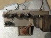
I have a Model 565 Voice of Music console that I need to recap and get going for sentimental reasons for a friend. It has a large GE Alumalytic QT4-3 cap in it. How do i replace this? Obviously I don't want nos.
 

Attachments

  • IMG_1624.jpg
    IMG_1624.jpg
    74.9 KB · Views: 57
Register to hide this ad
Usually those can capacitors that are hanging by wires and are not in the metal cans means that your amplifier is a series string (or hot chassis) amplifier.

I'll guess that the voltage ratings are 150 WVDC.

Show us the whole unit please. :yes:
 
new pics

sorry for the delay in the pics. Thanks for helping.
 

Attachments

  • IMG_1635.jpg
    IMG_1635.jpg
    95.3 KB · Views: 25
  • IMG_1634.jpg
    IMG_1634.jpg
    106.1 KB · Views: 28
  • IMG_1633.jpg
    IMG_1633.jpg
    91.2 KB · Views: 27
  • IMG_1632.jpg
    IMG_1632.jpg
    113.8 KB · Views: 29
  • IMG_1631.jpg
    IMG_1631.jpg
    93.1 KB · Views: 37
4 individual capacitors mounted to a terminal strip would do it. Two 22uf and two 47uf at whatever the right voltage is. That looks like something with a real power transformer, so you'll probably want 450v caps. What I'd personally do is find yourself a terminal strip with at least 5 terminals to mount to the chassis basically where the old cap was. Cut the wires from the old cap, land them on the terminals, and hang your new capacitors to that. Just watch that you don't land a wire on a grounded mounting tab.
 
A picture tells a lot. Interesting that it does in fact have a power transformer. Usually, amps and such with power transformers have the can capacitors mounted on the chassis.

I am still amazed at some of the designs that I have never seen before. I have seen thousands of VM amps but not one like this. Pretty cool!
 
drawing needed

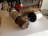
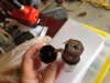
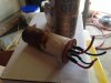
I opened the big cap to see what I am dealing with. While I tried not to destroy the old cap, I need functionality a lot more than keeping everything in stock appearance. Unfortunately, I did not learn anything once I opened up the cap.

My question is: How do I connect 4 new caps to equal the one old cap. As a bottom level hobbyist, I can copy what I am shown, so any crude drawing would be much appreciated.
 

Attachments

  • IMG_1640.jpg
    IMG_1640.jpg
    65.7 KB · Views: 19
  • IMG_1641.jpg
    IMG_1641.jpg
    69.7 KB · Views: 14
  • IMG_1642.jpg
    IMG_1642.jpg
    67.8 KB · Views: 12
  • IMG_1643.jpg
    IMG_1643.jpg
    56.6 KB · Views: 13
I am working on something similar- multiple wires, and the common negative "black." I did the strip mounting as suggested- is the black ground here?
 
The wires from the old cap should be color coded,,, connect a new cap of the correct value to the corresponding wire from the old can... bundle the new cap ground wires together, and connect them to the ground wire from the old can...
As stated previously, try to mount teh new caps, where the old can was, to help eliminate hum/noise...

Regards,
John

 
I am working on something similar- multiple wires, and the common negative "black." I did the strip mounting as suggested- is the black ground here?

Appears 30uF is Blue, 16uF Red,,, I assume black is ground, but it can be easily traced and confirmed...

Regards,
John
 
Back
Top Bottom