• The move to the new server is done. There are some software and database maintenance updates in process. This has us passing the hat around to help out. We appreciate any donations. Seriously, even a dollar helps. The payment page may be found here - https://www.audiokarma.org/support.html

VR resistor question

Rymdis

Member
Hi there!

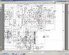
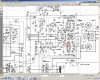
I have a burned one 100 ohm VR resistor and was wondering it that could be replace with a 1k ohm resistor? I have marked the VR with a red circle on the pictures. This VR adjust the idle current. I have no idea what will happen if i use a bigger one :) Mybe some wiz can help me out looking at the schematics. Its in an Pioneer SX550. It will be harder to pinpoint the exact current but i just wondering if its safe to use a 1k VR?


Many thanks
 

Attachments

  • sx1.jpg
    sx1.jpg
    128 KB · Views: 19
  • sx2.jpg
    sx2.jpg
    139 KB · Views: 14
Last edited:
Register to hide this ad
A designer will target a pot to have a useful range on it's adjustment. If it was mid scale, then it was using about 50 ohms.

Ideally, you'd check an identical one in another part of the circuit and see if that's about right. Then take your 1K pot (you are referring to using a pot, right?) and see if with an ohm meter you can comfortably adjust it in the 50 ohm (or whatever value is really in use) range. Chances are, that'd be difficult and it'd be tough to get a reliable value and be risking the output transistors.

So while you can possible achieve the running value, adjustment would be very touchy and tough to have be very stable. Not really such a good idea when you can wait a few days and get a correct value and not risk further problems!

Good luck and hope that's all the issues you've got in there!

Mark
 
Thanks for the answers!

Yeah, this amp is a mess, thats for sure :) But using a 1k Pot wont destroy anything, right? And i could see if adjusting it to 50ohm and around is very tricky.
ill see if 0-100ohm is out of range when turnings it. But if i manage to get it right, will it not be stable then?


/R
 
Last edited:
The slightest twitch will overbias the output stage, and you'll have a rather dead amplifier. Not recommended. Get the proper part.
 
But if i turn it to 50ohm just for testing pruposes, then that would be ok, or? I wouldnt touch it when its on as i saw it was VERY sensitive :)

/R
 
Put a 4.7~10 ohm resistor in there if you just want to test for functionality.

cool! As im no electrician i have to ask how to put this resistor. The Pot has three legs. In which two holes should i solder it? When i check the Pot there are two legs that gives the maximum resistance of that pot. is it in these two holes i should put the resistor?

thanks
 
Last edited:
Can't tell from here, but two of the holes where the original trimpot was mounted are likely on the same foil trace. One side of the resistor would go here (either hole, since they are at the same electrical potential), and the other side to the third hole.

If you get this wrong, Bad Things™ will happen.
 
Can't tell from here, but two of the holes where the original trimpot was mounted are likely on the same foil trace. One side of the resistor would go here (either hole, since they are at the same electrical potential), and the other side to the third hole.

I dont know the term "foil trace" :(

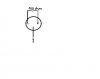
but ive made a pic of a pot that ive numbered the legs. from what i understand the resistor should be either in hole 1 or 2 and in 3? I took a 100 ohm pot as example.

and why use such low as 4.7~10 ohm resistor ?


thanks for the help. really appreciate it!!!
 

Attachments

  • pot.jpg
    pot.jpg
    16.9 KB · Views: 10
Look at the back (solder-side) of the board. Two of the traces should be on the same foil.
 
ah, you mean the copper-foil? From Sweden so i have some problems with these terms :(

Yes, there are two pins on the same copper-segment and one pin on another. Should one leg of the resistor be in one of the two holeson the same copper-sgement amd the other leg in the other hole then?

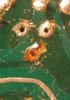
ive attached a pic where the pot used to be. Sorry for nagging but i just want to be sure here :)

the two left are on the same foil and the right one is on another.

and is there a reason to use such a low resistor?


thanks
R
 

Attachments

  • pot2.jpg
    pot2.jpg
    32.5 KB · Views: 9
Last edited:
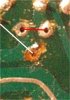
The single resistor needs to be mounted in the position of the "red" line. The white line is pointing to a torn foil trace.You will need to do a little repair work there when the time comes...
 

Attachments

  • pot2.jpg
    pot2.jpg
    26.9 KB · Views: 6
The single resistor needs to be mounted in the position of the "red" line. The white line is pointing to a torn foil trace.You will need to do a little repair work there when the time comes...

ok, thanks. But i dont understand why to use a low 4-10 ohm resistance here? What is the benefit?

yeah, some repair is on the way :)
 
Back
Top Bottom