• The move to the new server is done. There are some software and database maintenance updates in process. This has us passing the hat around to help out. We appreciate any donations. Seriously, even a dollar helps. The payment page may be found here - https://www.audiokarma.org/support.html

VTA Upgrade to Dynaco ST-70 problem.

W0ALA

New Member
I recently upgraded an early Dynaco ST-70 with the VTA Octal driver board kit. I am having a distortion problem that I have had a problem finding. It seems that I have a really harsh bit of distortion on the right channel that sounds like the upper bass and lower midrange at 450hz to 1khz. with the source down around .3 mv. The amp has had all the caps replaced and all of the resistors replaced. Also the Russian PIO caps that I purchased with the kit had been replaced with Mundorf MCap Supreme EVO 1000v .22mf caps. I have tried several different brands of caps but that is not the problem.
Any direction will be much appreciated.

Tony
 
Register to hide this ad
I don't know the 70 so I am just throwing this out. Maybe some type of oscillation? Do you own a scope?
 
I do own a scope and a function generator as well. I have put them on the system and other than some ripple on the output I'm not seeing much. I monitor the input as well as the output and there is amplification and some power line ripple. I have changed the sets of tubes and caps to no avail. Looks good but sounds really harsh if there is any volume at all. Also just to clarify when I have been using the scope I have had the amp attached to the dummy loads.
 
Are you using the 6sn7 board with the original Dynaco power trany? Doesn't the 6sn7 draw more heater current than the 12au7?
 
Check bypass resistors. I just had a similar problem with a Scott 299C where I mistakenly replaced to 2.7k with 270k resistors. Same symptoms. Loss of gain and distortion in a portion of the frequency band like you describe. I cleaned my bifocals, replaced the resistors with proper value and voila. Plenty of gain across the full range of frequencies..
 
Check bypass resistors. I just had a similar problem with a Scott 299C where I mistakenly replaced to 2.7k with 270k resistors. Same symptoms. Loss of gain and distortion in a portion of the frequency band like you describe. I cleaned my bifocals, replaced the resistors with proper value and voila. Plenty of gain across the full range of frequencies..
I did double and triple check the resistors and did in fact sent several pictures to Roy at Tubes4hifi and I believe he also included Bob Latino in the series of emails we exchanged. I did change the value of R39 as per Bob's instructions. Still no matter what source I've used I get the hard sound on the upper bass and lower midrange.
 
Last edited:
Are you using the 6sn7 board with the original Dynaco power trany? Doesn't the 6sn7 draw more heater current than the 12au7?
No I did install a new PA060 from Dynakit Parts as per Roy's recommendation for using the VTA Octal Driver Board Kit.
 
IMG_8687.JPG

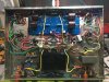
This is the underside of the chassis after the new board/Transformer install and the new caps. The only thing that has not been changed on this amp is the choke and the output trans. Of yea and the tube sockets.
 
Have you ruled out the speaker? I had a rotten foam woofer surround once that sounded like a buzz and it drove me nuts till I pulled the grill and saw the cracks in the surround.
I have tried a couple of speaker sets I have. I have a cheap set of Micca on the bench and a set of Onkyo on my home theater speakers. Both are marginal but before I put the updated driver board and rewired the amp they sounded great.
 
It's probably just the lighting, but the resistor on the left, bottom of the board next to that small electrolytic cap looks burnt. And the the one on the right looks discolored on one end. I dislike those sockets on the front for checking the bias, way to close to the board.
 
That is the resistor I changed to allow me to bias several different EL34/6CA7's. The original value 6.8k would not let me reduce the bias current low enough to Bias a set of JJ6CA7. What you are seeing is where I have yet to clean the flux off the board and resistor.

Thanks guys for all your comments and insight. I'm still trying to track down the problem.
 
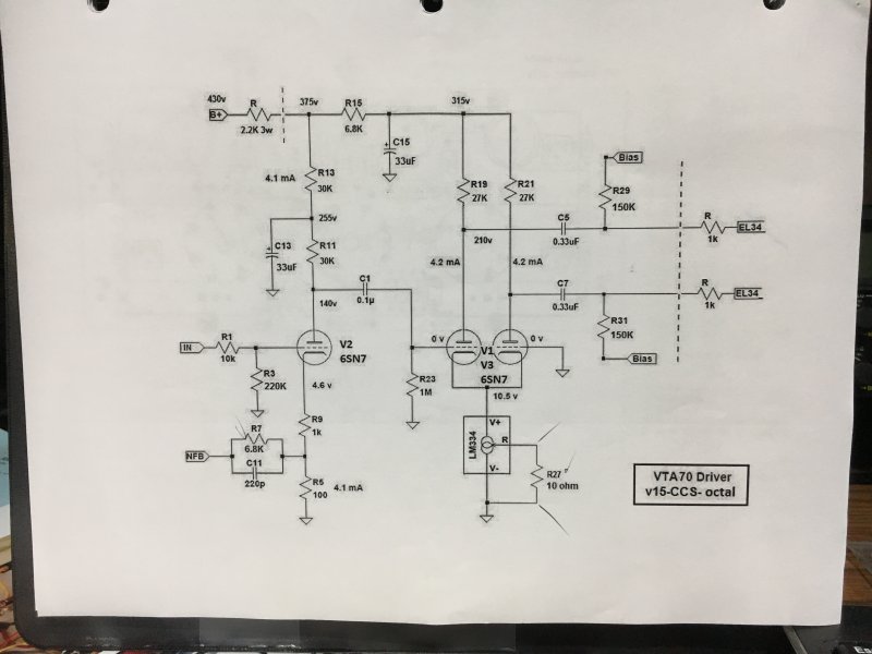
Can you verify that the CCS on the inverter stage is doing what it should? If that voltage is off, the phase inverter balance probably won't be right and that could cause some distortion. You should be seeing right near 200v on the plates of the inverter.
 
I got an octal driver board kit for my VTA ST120. I originally ordered from Roy but he was out of stock and so Bob sent the kit. Construction and replacement of the noval board were easy. My problem was I couldn't bias the amp for my KT88 tubes. Roy suggested that in lieu of the 7.5K ohm R39 to use a jumper and that the value of 270K for R29, 30, 31, and 32 was too high. I don't recall now what value Roy recommended but is was quite a lot less. I didn't want to have to remove the board to change these resistors obscured on the top of the board by the chassis cut out, so I tacked on appropriate value resistors in parallel on the bottom of the PCB to get the recommended resistance values. I can now bias the tubes properly. Fortunately, for me there were no distortion issues after the change. I do prefer the 6SN7GTB and the Black Treasure CV181Z drivers I am now using, Woala, good luck with finding your problem.
 
Have you swapped the left channel 6CA7 tubes with the right channel 6CA7 tubes to see if the problem follows?

JJ's?
 
Can you verify that the CCS on the inverter stage is doing what it should? If that voltage is off, the phase inverter balance probably won't be right and that could cause some distortion. You should be seeing right near 200v on the plates of the inverter.

VTA70-Octal.png

At R11 its 137v and at R12 its 137v same at P1 and P2. The voltage feeding into R11 and R12 is 261v. B+ is 386v.
 
At R11 its 137v and at R12 its 137v same at P1 and P2. The voltage feeding into R11 and R12 is 261v. B+ is 386v.

Hm, B+ is low according to the schematic. Its calling for 430. Being 50v low to start with, the other voltages would also be off. That actually may be the root of the problem. Methinks it would be worth checking your main power supply voltages. If the rectifier is tired or if something else is causing the low voltage none of this is going to work as expected.

The inverter plates would be off R19 and R21, and whatever the equivalent is on the other channel. R11 is the plate resistor for the voltage amp stage. That one seems OK. Schematic calls for 140, 137 is plenty close enough.
 
Back
Top Bottom