• The move to the new server is done. There are some software and database maintenance updates in process. This has us passing the hat around to help out. We appreciate any donations. Seriously, even a dollar helps. The payment page may be found here - https://www.audiokarma.org/support.html

VTL tiny triode 25 limited edition

Will2225

AK Subscriber
Subscriber
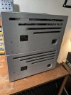
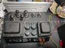
Picked up something interesting today. 4 VTL tiny triode limited edition amplifiers. They are el84 amplifiers and are apparently quite rare, only about 500 made.

I wasn't able to demo them but the owner said they worked. In testing one of them works perfectly, two of the other ones work but have a fairly loud hum and the last appears to have such a loud hum that I turned it off almost immediately.

They all passed the dim lightbulb test. I think they are probably about 20 to 25 years old at this point.

Ive repaired some tube amps before but because it appears these are rather valuable I think it might be better if I pay a tech to work on them.

Does anyone know of a tech in New England or the greater Boston area that they would recommend?

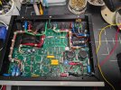
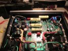
They don't look too complicated but I haven't opened them up yet.

Even with the hum they sounded excellent. I'm assuming they just need a recap, possibly new tubes,nwhich I could probably do myself if I can't find a tech.

I emailed VTL to see if they had information on biasing them. They have individual fixed bias adjustments and from what I've read I think the bias should be set to 200mv but I'm not a hundred percent sure
 
Register to hide this ad
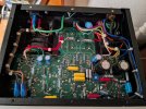
Still quite dusty and in need of cleaning. I have four of them even though only two are shown here.
 

Attachments

  • PXL_20250427_002815301.jpg
    PXL_20250427_002815301.jpg
    107.6 KB · Views: 126
  • PXL_20250427_002942915.jpg
    PXL_20250427_002942915.jpg
    172.8 KB · Views: 125
  • PXL_20250427_002951472.jpg
    PXL_20250427_002951472.jpg
    163.9 KB · Views: 124
  • PXL_20250427_002959684.jpg
    PXL_20250427_002959684.jpg
    161.4 KB · Views: 119
That is a nice find.

yes, quite spot on. You have the series II version. In working condition these amps sell fast. Lots of folks looking for them.

I have owned both the series 1 and series 2 version of the TTs. Pretty nice little amps with the right speakers.

If you have hum you may want to measure the power supply caps for ESR. They could need replacing. Not too difficult to do but requires a bit of time.

check on mouser or digikey and order same size and values as the originals.

you also may want to consider replacing those coupling caps with something better.
When I had mine, I ran the Russian EL84M tubes in them.
They were pretty trouble free amps.
 
The power supply caps look very easy to replace. I'll try to measure the esr and look into replacements. Shouldn't be that difficult. They really don't look that hard to work on.

Do you remember the right bias voltage? I think it's 200mv but I'm not really sure.

The hum in two of the amps isn't terrible but it's definitely worth fixing. Another one has no hum or hiss and then the fourth definitely needs some work.
 
I don't remember what the values are. But they are 450VDC rated snap mount for the main power supply caps.
I would Nichicon or Chemi-con 105C rated snap mounts. They should last longer than the stock parts.

Don't forget there are smaller value electrolytics on the board as well.

If you want you can add a few .01uf film bypasses to the power supply caps.

see attached.
 

Attachments

  • IMG_1151 VTL TT w Jupiter caps and PS bypass caps.jpg
    IMG_1151 VTL TT w Jupiter caps and PS bypass caps.jpg
    139.4 KB · Views: 60
Thanks for the advice. I just have to measure and make sure I get the correct lead spacing for the large caps.

I also will have to take a closer look at the board and see how difficult it will be to remove the entire thing to work on if I want to replace all the electrolytic caps. I'm not sure if I'll change the coupling caps or not. If I take the whole board out to work on I might as well.

I could probably replace the large capacitors in the power supply with the board in place and just moving around a few wires.

Hopefully VTL will respond to my email with the correct bias value.
 
So I took one of the monoblocks apart so that I can recap it. I also looked at the power supply caps and they look like they have a 10mm lead spacing.

I wrote down a quick list of the electrolytic capacitors to replace.

2x 47uf 100v 105c
1x 2200uf 16v 85c
2x 68uf 450v 85c 10mm lead spacing snap ins

The four 270uf 400v 85c 10mm lead spacing power supply caps

And then 4 0.22k 400v coupling caps.

I'll look into parts today and hopefully place an order.
 
Thanks for the advice. I just have to measure and make sure I get the correct lead spacing for the large caps.

I also will have to take a closer look at the board and see how difficult it will be to remove the entire thing to work on if I want to replace all the electrolytic caps. I'm not sure if I'll change the coupling caps or not. If I take the whole board out to work on I might as well.

I could probably replace the large capacitors in the power supply with the board in place and just moving around a few wires.

Hopefully VTL will respond to my email with the correct bias value.

Most snap mount caps use a 10mm spacing on the leads. You may not have to remove the board to replace the power supply cap.
Flip the amp over, remove the bottom cover and you should have access to the cap solder joints. If you remove all the solder, gently push the snap mount leads out and remove the cap from the top side of the amp. When installing new caps it may be trickier to align the PCB cap holes with the cap leads.
 
Most snap mount caps use a 10mm spacing on the leads. You may not have to remove the board to replace the power supply cap.
Flip the amp over, remove the bottom cover and you should have access to the cap solder joints. If you remove all the solder, gently push the snap mount leads out and remove the cap from the top side of the amp. When installing new caps it may be trickier to align the PCB cap holes with the cap leads.

I'm pretty sure I could replace the four filter caps on the other amps without taking the board out but I already disassembled it on this first one. It was a little difficult but definitely doable.

One thing I was confused about after unscrewing everything is how to remove the bias points which sit on top of the top panel. They ended up just popping out. Hopefully I can just press them back into place during reassembly.
 
@mcgjohn do you what the fifth bias point is for? The one that's separate from the rest. There's also one trim pot on the underside of the board that I'm not sure what it's for.
 

Attachments

  • PXL_20250429_150817151.jpg
    PXL_20250429_150817151.jpg
    164.7 KB · Views: 42
@mcgjohn do you what the fifth bias point is for? The one that's separate from the rest. There's also one trim pot on the underside of the board that I'm not sure what it's for.

cool. you got the board out. I see 4 bias points. Its been a while but that 5th point may be a ground connection to the ground plane of the amp. Am not 100% on that though.
 
That's the plan. Just waiting on parts and for when I have enough time to do it. Pretty busy this week.
 
Ordered the wrong size filter caps by mistake so I'm in the process of returning them. The correct sized caps came today. Nichicon LGX series, part number LGX2G271MELA40.

They are smaller than the original. Same value but a higher temperature rating, 105C instead of 85C. Hopefully they will work well. Going to try to recap the first amplifier today and reassemble.
 
Tried recapping the unit and reassembling it. Ran into an issue. When I first powered it on I used a dim bulb and there were no issues. Unfortunately I'm getting about -600v on all of the bias points. No smoke and nothing obviously fried.

I tried using 0.1uf film bypass caps on two of the large capacitors and ended up clipping them out to see if that was the issue but it wasn't.

All of the caps seem to be the right value and in the right orientation. Must be something wrong with the way I wired it.

I think maybe something is touching something it's not supposed to. I'm not a hundred percent sure I reinstalled the RCA jack correctly but I don't think this would cause the issue.
 

Attachments

  • PXL_20250505_214254518.jpg
    PXL_20250505_214254518.jpg
    146.8 KB · Views: 25
Back
Top Bottom