• The move to the new server is done. There are some software and database maintenance updates in process. This has us passing the hat around to help out. We appreciate any donations. Seriously, even a dollar helps. The payment page may be found here - https://www.audiokarma.org/support.html

Wafer correct position (Dolby) Sansui 9090DB

Dawid Ratal

New Member
Hello all,
I have a huge request for your help. I forgot to take a picture before the correct position of the Dolby wafer switch (pcb board F-2655). the receiver is a Sansui 9090DB in the 230V version.
Does anyone of you have photos or knowledge of how it should be properly set up? I'm sure I made a mistake and it certainly shouldn't be in the position it is in the pictures. I am only asking for help how the position of the first wafer in the "Dolby FM" position should look like.
1672646234486.jpg
1672646234496.jpg
1672646234506.jpg

I will be grateful for your help.
 
Last edited:
Register to hide this ad
Welcome to AudioKarma Exclusively Sansui. I think this thread has has the wafer order. You can find answers to many questions using the "Search Forum" tool at the top of main page.

- Pete
 
Welcome to AudioKarma Exclusively Sansui. I think this thread has has the wafer order. You can find answers to many questions using the "Search Forum" tool at the top of main page.

- Pete

Hello Pete,

Thank you very much for your answer. Not a simple topic. It turns out that this wafer (from the article) that you posted under the link is completely different than mine. That's why it's not that simple. Does Sansui for 230V have a different wafer from Dolby? I found another article but I'm still not entirely sure.

https://audiokarma.org/forums/index.php?threads/restoring-uncles-sansui-9090db.821650/page-4

In one picture you can see the wafer arrangement which is "OFF" on Dolby. See that there is a difference between what you sent.

All the Best!
David
 
David, do you know which wafer is which - in other words do you know the order of the wafers from the front of the switch to the back?

If you do, there are only 2 positions for the 'wiper' in each wafer when inserting the switch shaft. From this starting point you could then find out what connections on the PCB each wafer makes (or breaks), and match the position of the wiper to coincide with these connections by referring to the schematic, (very tedious). Unfortunately you'll need to do this for each wafer in turn - and it depends on you knowing the wafer order as above.

I would warn against guessing and experimentally installing the switch and wafers, as if you solder them in, and then have to remove them again you could damage the PCB traces - and that would be even more of a nightmare.

If you don't know the order of the wafers then I have nothing more for you - other than to keep searching for more pictures of the switch assembly.

Good luck.
 
Hello Pete,

Thank you very much for your answer. Not a simple topic. It turns out that this wafer (from the article) that you posted under the link is completely different than mine. That's why it's not that simple. Does Sansui for 230V have a different wafer from Dolby? I found another article but I'm still not entirely sure.

https://audiokarma.org/forums/index.php?threads/restoring-uncles-sansui-9090db.821650/page-4

In one picture you can see the wafer arrangement which is "OFF" on Dolby. See that there is a difference between what you sent.

All the Best!
David
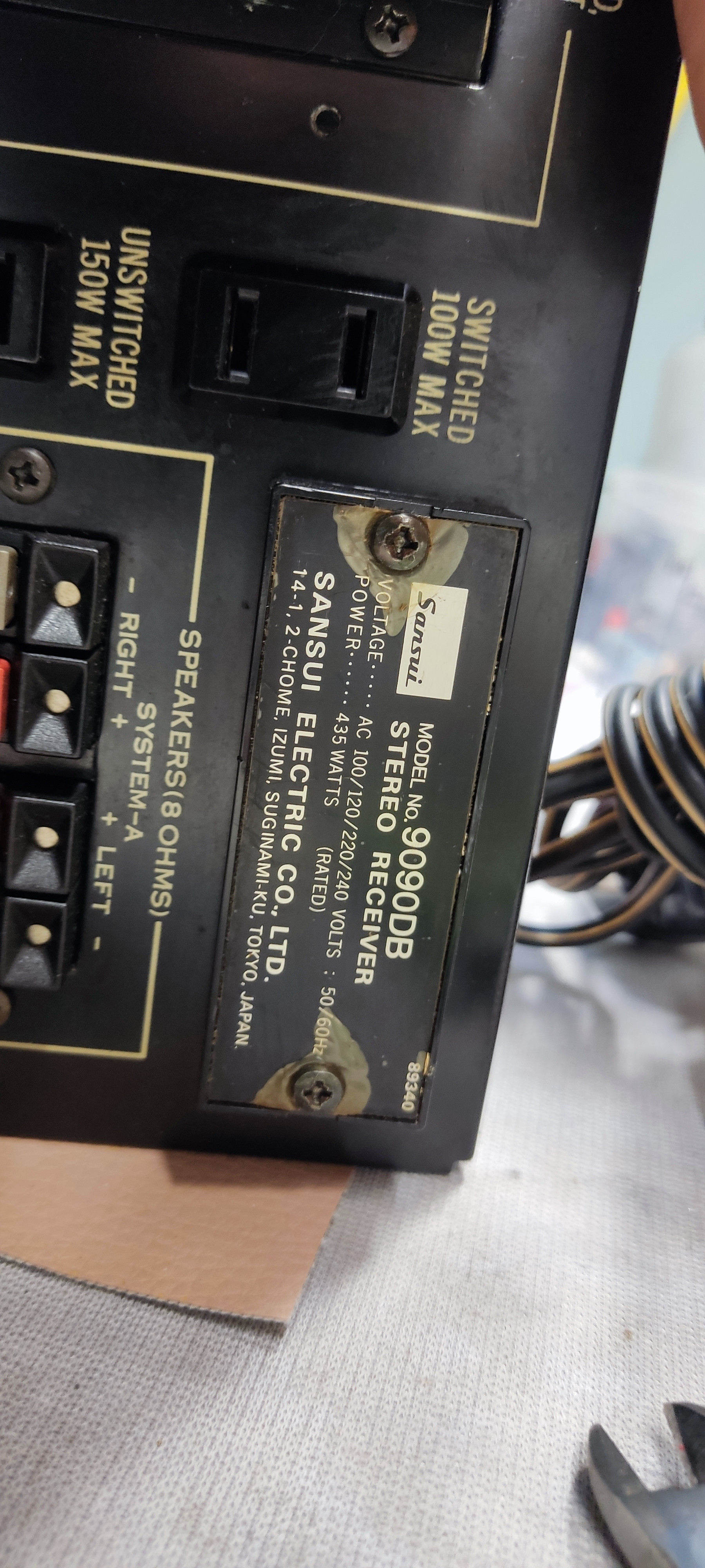
Sansui is famous for not documenting production changes so it is possible that your Dolby switch is different. Most Sansui "export" models have a voltage switch and can accept 4 different input voltages. I've never seen an exclusively 230V 9090DB. Can you post the serial number and a picture of the identification plate on the back panel? I'd like to document it in the database.

- Pete
 
Sansui is famous for not documenting production changes so it is possible that your Dolby switch is different. Most Sansui "export" models have a voltage switch and can accept 4 different input voltages. I've never seen an exclusively 230V 9090DB. Can you post the serial number and a picture of the identification plate on the back panel? I'd like to document it in the database.

- Pete

Hello Pete

Of course adds them. Here you are :)
1672914731899.jpg
1672914731910.jpg
 
The voltage switch (plug) is under the cover with the model # on it. Just take out the two screws to access it. It is a plug assembly that you plug in different configurations to set the voltage.
 
Thanks for posting the pictures. There is nothing unique about your 9090DB. It's a standard "export" model with the capability of 4 different input voltages. It was the 1966th unit off assembly line 81 in March of 1977. Sansui made 10s of thousands of 9090DBs. It may have had the power cord changed at some point but other than that it should be identical to the others made at that time. Based on the serial numbers in the database, Production line 81 was just building 9090DBs and the black trim version 990DBs that month. The highest production number on file for that month is 3945. Sansui was selling a lot of 9090DBs in 1977.

Sansui made 10s of thousands of these 9090DB export models. It may have had the power cord changed at some point but other than that it should be identical to the others made around that month. The chassis will be plain zinc plating and unless the driver board was replaced at some point it will have transistor bias control. Based on the serial numbers in the database, production line 81 was just building 9090DBs and the black trim version 990DBs that month. The highest production number on file for that month is 3945. Sansui was selling a lot of 9090DBs in 1977.

- Pete
 
Hello all,
I have a huge request for your help. I forgot to take a picture before the correct position of the Dolby wafer switch (pcb board F-2655). the receiver is a Sansui 9090DB in the 230V version.
Does anyone of you have photos or knowledge of how it should be properly set up? I'm sure I made a mistake and it certainly shouldn't be in the position it is in the pictures. I am only asking for help how the position of the first wafer in the "Dolby FM" position should look like.
1672646234486.jpg
1672646234496.jpg
1672646234506.jpg

I will be grateful for your help.
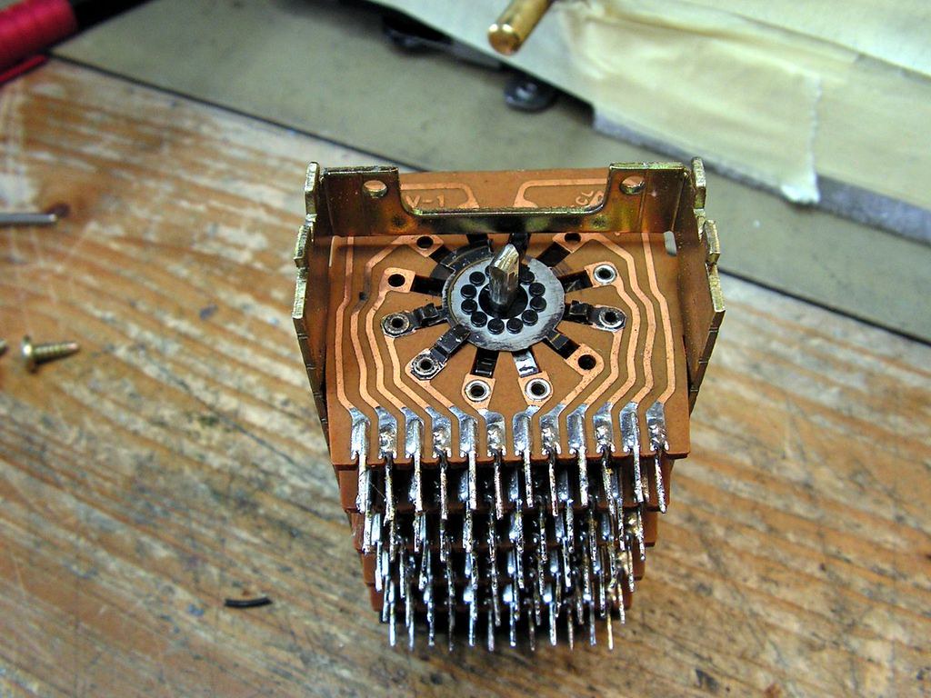
Left to Right = Front to Rear.. Front and back of the wafers.0211211938a.jpg 0211211938b.jpg 0211211938c.jpg 0211211939.jpg 0211211938a.jpg

Tiny burrs on the front of the shaft helps keep it from walking out over time.
 

Attachments

  • Wafer switch shaft burrs added.jpg
    Wafer switch shaft burrs added.jpg
    96.4 KB · Views: 18
Back
Top Bottom