• The move to the new server is done. There are some software and database maintenance updates in process. This has us passing the hat around to help out. We appreciate any donations. Seriously, even a dollar helps. The payment page may be found here - https://www.audiokarma.org/support.html

Welborne Labs ST70 Mod

If those zeners are in the bias supply, TAKE THEM OUT! Do not replace them with anything. I've worked on more than one ST-70 that had a Welborne power supply board in it (different from the one you guys are working on), and each side's bias supply circuit had a zener running from positive to ground in an attempt to keep the bias supply fixed at a specific voltage (can't remember off top of my head). The problem comes from the need for the bias voltage to be able to move up and down relative to all the other voltages in the amp, which it cannot do with the zeners in place.
 
welborne st70 Mod

Hi Shelly,

Thanks for your help. The problem is that the only voltage given in the instructions are for the B+ approx. 410v and -65v for bias measured between r31 and r33 for R channel and R32 and R34 for the L channel. The rectifier tube is fine.
Ron just emailed me back and stated that r45 and r46 should be 620 ohm/2W!!! So after reviewing the first manual I had gotten with the welborne board I realized that I had 200 ohm/2W resistors in the r45 and r46 position (which is what was included in the parts list). Anyways I will be ordering replacements for the fried parts and will try again with the proper value resistors. I can't believe I missed that again and again!
Perhaps removing the zeners in the bias supply would be a wise choice as well - Thanks Don.
If Brio is listening in Check your R45 and R46 resistors!!!!
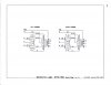
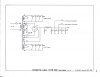
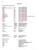
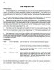
I have included scans of schematics.

Daryl

Thanks all and wish me luck!
 

Attachments

  • st70driverstage.jpg
    st70driverstage.jpg
    148.5 KB · Views: 135
  • st70outputstage.jpg
    st70outputstage.jpg
    88.3 KB · Views: 111
  • st70powersupply.jpg
    st70powersupply.jpg
    94.5 KB · Views: 108
  • st70partslist.jpg
    st70partslist.jpg
    186.6 KB · Views: 111
  • st70fireupandtest.jpg
    st70fireupandtest.jpg
    110.6 KB · Views: 107
Hi,

I replaced all compromised parts as noted above. Resistors R45 and R46 were changed to 620 ohm from the original 200 ohm. The amp is working perfectly!!!!! Thanks for everyone's help. As an aside, I was in contact with Ron Welborne and he sent me replacement parts for the ones that had failed in the original build (in addition to a few parts I had ordered). Nice to see him making an effort to remedy the situation. Hopefully things are getting sorted out with his business.
Good music to all.

Daryl
 
Welborne st70 !&@#%#!#%!^%!^#!!!!!!

I spoke too soon.
The bias on the right channel rose to 16v and would not adjust down with the trim pot. The right channel emits a very, very low level of signal - barely audible. The b+ voltage now sits at 480v rather than the 430v I had after replacing the resistors and caps. I am about ready to put the welborne board in the trash bin. I swapped output tubes to the opposite channel, then tried a different rectifier, then swapped the driver tubes - still the right channel will not bias properly.
There was no smoke, no hot capacitors????
Any recommendations on a st70 board that works well and sounds good?

^@%^%@^%@*%@*%$#@#@@@##$%^&*(

Daryl
 
I spoke too soon.
The bias on the right channel rose to 16v and would not adjust down with the trim pot. The right channel emits a very, very low level of signal - barely audible. The b+ voltage now sits at 480v rather than the 430v I had after replacing the resistors and caps. I am about ready to put the welborne board in the trash bin. I swapped output tubes to the opposite channel, then tried a different rectifier, then swapped the driver tubes - still the right channel will not bias properly.
There was no smoke, no hot capacitors????
Any recommendations on a st70 board that works well and sounds good?

^@%^%@^%@*%@*%$#@#@@@##$%^&*(

Daryl

I know this is a bit of heresy in this forum but I use the stock board with outboard bandwidth limiters as described by Frank Van Alstine. You can find the article here:

http://www.enjoythemusic.com/Magazine/manufacture/0902/index.html

I used the formulas he presents and spreadsheet to spread the pass band of the filters out to about 17Hz to 21,000 Hz. It sounded great till my PS caps went south taking my rectifier and power transformer with it.

The mod is cheap. If you still have the original circuitry and want to try it I would say go for it. Lots of folks here disagree with my evaluation of this mod but it would be much cheaper then a new mod board and components. Who knows - you may like it.
 
I spoke too soon.
The bias on the right channel rose to 16v and would not adjust down with the trim pot. The right channel emits a very, very low level of signal - barely audible. The b+ voltage now sits at 480v rather than the 430v I had after replacing the resistors and caps. I am about ready to put the welborne board in the trash bin. I swapped output tubes to the opposite channel, then tried a different rectifier, then swapped the driver tubes - still the right channel will not bias properly.
There was no smoke, no hot capacitors????
Any recommendations on a st70 board that works well and sounds good?

^@%^%@^%@*%@*%$#@#@@@##$%^&*(

Daryl

I built the Welbourne mod in the mid to late 90's. It fired up perfectly, ran perfectly and measured perfectly. Still works just fine. Wank owns it now and seems to be working just fine for him as well. The instructions are horrible, and it wasnt an ideal "2nd" project in terms of simplicity.

I also had a failed bias pot. Replacement cured the problem. ( Knob went round and round but didnt change reading.)

Russellc
 
welborne labs st70 mod - singing sweetly!!!!!!

It has been three weeks since I replaced the bias pot along with a couple of resistors/caps in the bias circuit and this thing is performing perfectly now!!!
I am quite pleased I hung in there and did not toss it in the trash bin. Thanks for the help from every body! Brio, did you ever get yours running?
Daryl
:banana::music:
 
re: ST70 Welborne driver/PS board overheating failure

I've been running a "new" ST-70 based a combination of the Triode Electronics chassis. PS choke and transformers with the Welborne
driver/PS board. The whole thing has worked incredibly well and is a
antastic amp, better than just about anything I've ever heard. I am using the standard 5AR4 rectifier tube, and initially, a set of Electroharmonix EL-34s. I do not run the amplifier to it's limits.
It is used as the upper range amp in a biamplified system driving the
midrange/tweeter sections of a pair of B&W 634 speakers usually driven
at sane volumes on a fairly small room.

It does seem to run pretty hot such that it is just about hot enough
to make it uncomfortable to bordering on painful to touch to aluminum
mounting plate. I do intermittently check the bias voltage which has
been stable varying very little from the target 1.5V setting.
For no clear reason, I've blown about 3 fuses over the last year.
Each time I replace the fuse, the amp runs fine for a period of months.

I have now had a failure of the amp. While listening, one of the
EL-34s (front right channel) began to show color on the plate
increasing over about a minute or so to bright orange then followed
by failure of the amp and a blown fuse. There was no flash or
sparking to suggest that a component "zorched." I replaced the fuse but the amp would not power up, blowing the fuse again. I've since replaced the EL-34s (all) with a matched quad of Mullards, replaced the fuse again and
another blown fuse without powering up.

I took out the Welborne driver board for closer inspection and the problem became evident. On my cursory initial inspection I did not appreciate the extent of the damage with the board still installed.

The sockets for V3 and V4 are melted and discolored brown. The V1 V2 sockets are still largely white but warped from heat. The resistors at the periphery of the V3 V4 sockets look OK, not cooked or discolored but the board is slightly darkened in the area surrounding these sockets. The two pairs of zener diodes adjacent to the bias pots appear severely heat damaged and discolored and the board on the non-component side adjacent to the pots and the diodes is blackened and charred (both channels), appearing to be the result of longstanding excessive heating, not an acute failure. Two PS electrolytics adjacent to these diodes that show puffing of the plastic covering material, apparently damage from heating. Two smaller C5,6 0.47 microfarad Solen caps next to the pair of larger 0.33 microfarad coupling AudioCaps also appear heat damaged with the covering material pealing off.

I'm wondering if it R 23 24 25 26 33K ohm cathode and plate resistors that are producing the heat that has severely damaged the V3 V4 tube sockets. Perhaps I could do better installing larger wattage resistors and installing them with very long leads elevating the units high (about 1/2 inch?) off the board surface.

I checked the R45 and R46 resistors and they are the correct 620 ohm 2 watt units.

Ron Welborne has been very helpful, promptly answering my email and offering to send parts to correct the bias problems. I am inclined to take the zeners out. An interesting option would be to install an voltage regulator chip in the bias line to provide a stable voltage and locate it off the board, bolted to the chassis for heat sinking. I plan to replace any and all the electrolytics that appear to be heat damaged.

Any thoughts?

 
I've been running a "new" ST-70 based a combination of the Triode Electronics chassis. PS choke and transformers with the Welborne
driver/PS board. The whole thing has worked incredibly well and is a
antastic amp, better than just about anything I've ever heard. I am using the standard 5AR4 rectifier tube, and initially, a set of Electroharmonix EL-34s. I do not run the amplifier to it's limits.
It is used as the upper range amp in a biamplified system driving the
midrange/tweeter sections of a pair of B&W 634 speakers usually driven
at sane volumes on a fairly small room.

It does seem to run pretty hot such that it is just about hot enough
to make it uncomfortable to bordering on painful to touch to aluminum
mounting plate. I do intermittently check the bias voltage which has
been stable varying very little from the target 1.5V setting.
For no clear reason, I've blown about 3 fuses over the last year.
Each time I replace the fuse, the amp runs fine for a period of months.

I have now had a failure of the amp. While listening, one of the
EL-34s (front right channel) began to show color on the plate
increasing over about a minute or so to bright orange then followed
by failure of the amp and a blown fuse. There was no flash or
sparking to suggest that a component "zorched." I replaced the fuse but the amp would not power up, blowing the fuse again. I've since replaced the EL-34s (all) with a matched quad of Mullards, replaced the fuse again and
another blown fuse without powering up.

I took out the Welborne driver board for closer inspection and the problem became evident. On my cursory initial inspection I did not appreciate the extent of the damage with the board still installed.

The sockets for V3 and V4 are melted and discolored brown. The V1 V2 sockets are still largely white but warped from heat. The resistors at the periphery of the V3 V4 sockets look OK, not cooked or discolored but the board is slightly darkened in the area surrounding these sockets. The two pairs of zener diodes adjacent to the bias pots appear severely heat damaged and discolored and the board on the non-component side adjacent to the pots and the diodes is blackened and charred (both channels), appearing to be the result of longstanding excessive heating, not an acute failure. Two PS electrolytics adjacent to these diodes that show puffing of the plastic covering material, apparently damage from heating. Two smaller C5,6 0.47 microfarad Solen caps next to the pair of larger 0.33 microfarad coupling AudioCaps also appear heat damaged with the covering material pealing off.

I'm wondering if it R 23 24 25 26 33K ohm cathode and plate resistors that are producing the heat that has severely damaged the V3 V4 tube sockets. Perhaps I could do better installing larger wattage resistors and installing them with very long leads elevating the units high (about 1/2 inch?) off the board surface.

I checked the R45 and R46 resistors and they are the correct 620 ohm 2 watt units.

Ron Welborne has been very helpful, promptly answering my email and offering to send parts to correct the bias problems. I am inclined to take the zeners out. An interesting option would be to install an voltage regulator chip in the bias line to provide a stable voltage and locate it off the board, bolted to the chassis for heat sinking. I plan to replace any and all the electrolytics that appear to be heat damaged.

Any thoughts?

If you search around you will find a post by bricktop I believe. The zeners are a problem, and can cause this red plating. apparently they dont allow the bias to vary up and down with the voltage.

Russellc
 
So I guess

So it would seem like if you remove those and do whatever circuit modifications bricktop et all recommended, and then ou replace all the crispy / suspect parts maybe you can bring it up slowly on a variac and see if you have things fixed.

Sorry to hear you had such a wide range of damage. I guess that is the sort of thing that made people thing solid state was better when it came out. (err like reliable better).

Dan
 
Thanks. I read the post you cite. I emailed an extensive note to Ron Welborne today. For one, I suggested using a 3 terminal IC voltage regulator in place of the zeners or just omit them entirely as some hve suggested. I think there are several 2 watt resistors in the cathode and plate circuits for V3 and V4 that are major heat producers, though nothing like the zeners, which I am inclined to mount high off the board with very long insulated leads.

I assume the sockets supplied with the board are made of the common Celanex PBT meaterial. If so, this board got really hot-- the melting point of the material is 225C, 437F.

Steve
 
Hi Steve,

I know it has been a few years since you posted regarding your st70.
Did you get your amp working properly? I would love to hear of any mods you did to get your amp stable. Did Ron offer any advice to rectify the problems?
The bias supply on mine overheated again and melted the 4 zener's solder pads, the .47uf Solen caps and bias trim pots.
Would be great to hear back!

Daryl
 
I doubt it. Back then when I talked to Ron it seemed he wasnt even familiar with it, the parts or how it went together. Its too bad as that was the best sounding ST-70 mod I ever had, and I had several.

Russellc
 
Back
Top Bottom