• The move to the new server is done. There are some software and database maintenance updates in process. This has us passing the hat around to help out. We appreciate any donations. Seriously, even a dollar helps. The payment page may be found here - https://www.audiokarma.org/support.html

Wells-Gardner / Wards Tube receiver

josephdaniel

vitam vivere pro teipso
This is going to be a long post with a lot of information!

I have a Montgomery Wards WG-2694A console that I have been working on for the past month in my spare time.
When I received it the amplifier section was working well, however the AM side would only receive our two local stations and the band is very quiet (no static). On the FM side there was a normal amount of static, but it wouldn't receive any stations.

I assumed there was a combination of weak tubes in the tuner section and possibly failed paper capacitors along the signal chain. All of the tubes tested fine on my simple emissions tester. I moved forward with ordering an appropriate assortment of replacements for the paper and electrolytic capacitors in the set hoping for an easy fix.

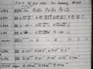
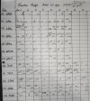
After recapping the set the amplifier works beautifully, however there was no change in the performance of the tuner. I checked the resistance at each of the test points notes in the schematic (see attached files) and there was nothing glaringly out of tolerance. I also checked some voltages throughout the tuner section.

I noted that the grid voltage of V2 (6AU6A) was positive which in my (likely flawed) understanding of the schematic points to a failure of the FM local oscillator. I checked with a second radio and could hear the AM oscillator running, but nothing coming from the FM side.

I tested the FM RF amp / converter tube (V1 ECC85) again to verify it's condition. I also cleaned the pins as best as I could. To no improvement. The tuner assembly is encased in a solder sealed box that is also soldered to the main chassis and will be very difficult to access without creating further issues.

After that I tested additional voltages around the tuner mostly (see attached file) and noted some irregularities. I am not well versed enough in electronic theory to full understand how each component in the circuit affect one another.

Any thoughts on where I should look next for my issue? I have a basic Heathkit IG-42 signal generator (I've never used it, but it's accurate according to my frequency counter) that I could use to inject a signal throughout the chain. I had thought about injecting a signal into the RF amp and then in the IF 1&2 to possibly narrow things down? However, I don't think there would be enough amplification in the circuit for it to do me any good beyond that point.

Help would be appreciated! I am still learning and trying to understand this stuff.

Attached is a copy of the schematic for this chassis, a copy of the voltage readings, and the resistance readings. On the table for the resistance measurements the values from the schematic are written on the right of each cell and the voltage measurements are formatted the same way.
 

Attachments
  • IMG_20240522_222457.jpg
    IMG_20240522_222457.jpg
    129 KB · Views: 10
  • IMG_20240522_222520.jpg
    IMG_20240522_222520.jpg
    106.5 KB · Views: 10
  • WG-2694A.pdf
    WG-2694A.pdf
    646.8 KB · Views: 14
Last edited:
Register to hide this ad
Good ol' Sams Photofacts. For "still learning and trying to understand" I'd say you're well on your way, pretty deep. Sorry no, I don't have a specific answer, just a few thoughts:
  1. Dumb question maybe, but did you connect a decent external antenna for both FM and AM? Schematic indicates connectors are there, usually screw terminals on back of unit.
  2. Presumably your location has a number of stations strong enough for the average receiver to pick up. Distant AM stations of course come in better at night.
  3. Back in the day "Monkey Wards" radios generally were considered to be low-budget quality (although as a teenager the Airline shortwave radio I inherited from my grandfather worked OK with a 75-foot long wire antenna above the roof--after my uncle the radio repairman replaced a bad cap). And that was around 1962. My point is that your Wards receiver's poor performance could possibly just be due to inherently low sensitivity; this spec is usually expressed in microvolts but I doubt it's published anywhere.
  4. Injecting a signal and tracing it through the circuitry is advanced diagnostics but might tell if some component other than a tube or cap is bad/weak, but at that level I think technicians would also use an oscilloscope. Your Sams schematic is essential for that but IDK what the "normal" benchmark readings would be.
Good luck! Let us know what you find out. Then with your level of knowledge and experience you'll be the expert compared to most of us!
 
Good ol' Sams Photofacts. For "still learning and trying to understand" I'd say you're well on your way, pretty deep. Sorry no, I don't have a specific answer, just a few thoughts:
  1. Dumb question maybe, but did you connect a decent external antenna for both FM and AM? Schematic indicates connectors are there, usually screw terminals on back of unit.
  2. Presumably your location has a number of stations strong enough for the average receiver to pick up. Distant AM stations of course come in better at night.
  3. Back in the day "Monkey Wards" radios generally were considered to be low-budget quality (although as a teenager the Airline shortwave radio I inherited from my grandfather worked OK with a 75-foot long wire antenna above the roof--after my uncle the radio repairman replaced a bad cap). And that was around 1962. My point is that your Wards receiver's poor performance could possibly just be due to inherently low sensitivity; this spec is usually expressed in microvolts but I doubt it's published anywhere.
  4. Injecting a signal and tracing it through the circuitry is advanced diagnostics but might tell if some component other than a tube or cap is bad/weak, but at that level I think technicians would also use an oscilloscope. Your Sams schematic is essential for that but IDK what the "normal" benchmark readings would be.
Good luck! Let us know what you find out. Then with your level of knowledge and experience you'll be the expert compared to most of us!
Thanks for the ideas!

I do have an antenna connected for both FM and AM. In my area there are only two local broadcast band stations, but most receivers that I own are able to pull in stations from other areas during the day and lots of DX'ing at night. On the FM side we have one station that is strong enough (or I am close enough to the transmitter) that I can tune in the harmonic frequencies throughout the bandspread - we have another half dozen or so local stations that can be picked up by the worst tuners as well. I am not expecting this to be a super sensitive receiver, but it should work well enough for local listening.

As far as the positive grid on V2 the only thing I can think to check would be if there is a coupling capacitor that is leaking from another plate or the grid is somehow open to ground (ruled out I think). I'm not sure if this is a red herring or not, but it seems like a good place for me to start. I'm open to suggestions.

If am understanding things correctly I should be able to inject a signal starting with wire wrapped around the antenna on the front end and then into pin #2 of V2, V5, and V6. If I get output on V5 then that would indicate a fault in the intermediate frequency amplifiers (and in this case possibly RF) before that point. I'd keep moving back throughout the circuit until I find the point at which the signal is lost. Theoretically this should be in the vicinity of the fault? When injecting a signal how important is the frequency, and what should I be injecting in the circuit? I can trace things out with my oscilloscope to visually follow things once I am oriented with how things should be flowing.
 
OK, then lack of good stations is not an issue like it'd be if you were on some remote Pacific isle. You say amp is fine (like for TT vinyl) and presumably you've deoxed switches.
Since you already know tubes and caps are good and test equipment is reliable, if coils, resistors, hermetically sealed box etc. are all good then only other thing I can think of is maybe alignment is out of whack or even bad solder joint. But I have no experience at that level.
Any clear AM or FM input frequency should be OK to trace. I've seen the wire wrapping injection technique used on a functioning unit before but obviously your receiver is attenuating the signal somewhere between antenna and loudspeaker. IDK if connecting signal generator directly to antenna input is better but might also be worth a try.
I know there're AK techies out there vastly more knowledgeable than I am, so hopefully somebody with tube restore experience can help.
 
I might want to consider swapping V1 for a known good old production tube. What this is being asked to do it may test OK on a basic tester but not function properly in-circuit. Radio stuff is a bit more abusive than the basic check that an emissions tester does.

that won't affect AM performance though.

if your signal generator will do a 10.7 mhz FM modulated output, try wrapping the output lead around V2 and see if you can get any signal through it. If it won't do FM, use a voltmeter to whatever point the schematic says to use for aligning FM using an AM signal generator. Probably point A. If its getting signal through you should see the voltage swing negative as you change the output level of the generator.
 
I might want to consider swapping V1 for a known good old production tube. What this is being asked to do it may test OK on a basic tester but not function properly in-circuit. Radio stuff is a bit more abusive than the basic check that an emissions tester does.

that won't affect AM performance though.

if your signal generator will do a 10.7 mhz FM modulated output, try wrapping the output lead around V2 and see if you can get any signal through it. If it won't do FM, use a voltmeter to whatever point the schematic says to use for aligning FM using an AM signal generator. Probably point A. If its getting signal through you should see the voltage swing negative as you change the output level of the generator.
Tonight I'll try and see if I can get signal into V2. The manual describes using an oscilloscope and provides waveform illustrations - sometimes visualizing things can provide a little more insight compared to looking at numbers on a meter. One thing, the service manual alignment process describes injecting a signal into pin 7 of the FM converter through a .001 mfd capacitor. I have examined the chassis carefully and I can't see a method to open the RF amplifier section without physically removing the entire FM tuner sub-chassis assembly.

I agree that substituting V1 would be a very sensible step. The tester that I have on hand is fairly basic and my 'good' one is several states away at the moment - even then things still preform differently in circuit depending on the characteristics. I don't have a spare on hand and those ECC85 / 6AQ8 tubes are a little spendy - I am working on this set for a friend and would prefer to eliminate that possibility before potentially wasting an additional $35 if I am moving in the wrong direction.
 
The waveform thing looks like an inverted U or roughly like a letter S ? Thats the alignment stuff using a sweep generator. If its got stuff for doing it with an AM generator it will be using a VTVM at some point for max voltage, and at another point for zero volts. Basically just looking to see if it responds when fed signal. If it does I might also suggest seeing if it has a sharp peak or not that is very near to wherever its currently set. If someone has been in here twiddling adjustments it will peak away from the current setting, if the IF transformer's internal caps have failed it either won't peak or it will be extremely broad rather than a very distinct point.


should be able to loop the output wire of the signal generator around the tube and get it to couple in well enough.

the fact that both AM and FM aren't working right really makes me wonder about all this, its not impossible that both bands have an issue but my inclination is more towards a common fault. Not much in common other than the 6BA6 though.
 
The waveform thing looks like an inverted U or roughly like a letter S ? Thats the alignment stuff using a sweep generator. If its got stuff for doing it with an AM generator it will be using a VTVM at some point for max voltage, and at another point for zero volts. Basically just looking to see if it responds when fed signal. If it does I might also suggest seeing if it has a sharp peak or not that is very near to wherever its currently set. If someone has been in here twiddling adjustments it will peak away from the current setting, if the IF transformer's internal caps have failed it either won't peak or it will be extremely broad rather than a very distinct point.


should be able to loop the output wire of the signal generator around the tube and get it to couple in well enough.

the fact that both AM and FM aren't working right really makes me wonder about all this, its not impossible that both bands have an issue but my inclination is more towards a common fault. Not much in common other than the 6BA6 though.
Agreed, I had initially suspected a common fault in the two.

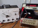
I did some poking around with the signal generator and have some informative findings. Here is what I found:

In FM if I inject a 10.7MHz modulated carrier wave into the grid (pin 1) of V2 6AU6 I heard a clearly audible tone from the speakers once the probes from my meter were removed from point A. Once I noted that I figured my little multi-meter was loading down the circuit. Just going off of the tone passing though the speakers I was able to figure that the strength of the signal out of the speakers peaks at approximately 11.5 Mhz and is consistent throughout the entire bandspread. I say approximately as I can not find a plain BNC cable to connect to my frequency counter - however, last time I had it hooked up the generator was fairly accurate off of the dial scale.

After noting this I assumed that everything downstream of V2 is more or less functional in the broad general sense. I went ahead and injected the same signal into into into the antenna connector. Boom same signal out of speakers, but weaker and with some slight background static. If I recall I had to move the step attenuator on the signal generator over one click from x100 to x10. The signal strength still seems to audibly peak at 11.5 MHz. At first I was thinking that the output of the signal generator was non-linear, but the meter on it is more or less in the same place at 10.7 as 11.5 MHz.

Now I am wondering - shouldn't the set "peak" at 10.7 MHz? If so it's odd that the alignment would be this far out - it doesn't look like anything around this set has ever been touched. All the tubes and capacitors are original. Now I am thinking that it may be best to go through the alignment procedure in the manual and see if there is any change. Perhaps someone in the past was a screw turner and did some messing around. I am now once again wondering if a fault in V1 6AQ8 / ECC85 could produce these symptoms.
 
the peak should be at 10.7. Now the question is whether its off because someone fiddled with it, or because the caps in the IF cans have failed and de-tuned them. Both are possible. The response should be your clue though, if the caps are good it will have a very sharp peak so long as you keep the generator level low enough. If the caps are bad it won't be sharp and overall gain will be lower than it should be. You can probably figure out how sharp it is with the sig gen, if its peaked at 11.5, it should be giving you basically nothing at 11.3 and 11.7 mhz. If its just a gradual peak and slight drop across that entire range something isn't right.


a problem in the 6qa8 wouldn't cause the IF strip to be nearly 1mhz off.
 

@gadget73 I made a short video showing the signal cutoff with what I felt is a pretty low level output from the generator being fed into the antenna connection. On the signal generator the band that I am reading is the innermost one "band E".
To me this seems like a fairly sharp cutoff, but I have always treated RF / IF sections like a mysterious black box of magic. This would indicate the silver mica caps in the cans have *not* failed?
 
Last edited:

@gadget73 I made a short video showing the signal cutoff with what I felt is a pretty low level output from the generator being fed into the antenna connection. On the signal generator the band that I am reading is the innermost one "band E".
To me this seems like a fairly sharp cutoff, but I have always treated RF / IF sections like a mysterious black box of magic. This would indicate the silver mica caps in the cans have *not* failed?
Well, no dice here. Turns out the signal generators dial face *was* inaccurate after all. I couldn't find a BNC cable to hook it up at the same time as the tuner. However I thought I could try clipping some leads that I have to an adapter and see what the real frequency is after finding the highest response from the set.

Surprise surprise - it's 10.7 MHz right on the dot. Back to square 1!
 

Attachments

  • IMG20240524152601.jpg
    IMG20240524152601.jpg
    108.9 KB · Views: 6
ok so the IF does seem fairly sharp and its on frequency, so its kinda has to be oscillator problems. Since its not showing up on a second radio that kinda confirms it. Not a whole bunch in there, if its not the tube itself there are only a handful of passive components.

A 6DT8 will also sub for a 6AQ8 and they cost less. Don't suppose you've got another FM tuner around with either tube you can borrow as a test ?
 
Nope, I already ordered a 6AQ8 right after seeing the IF being on target. All I have on hand for RF that I can find is a 6J6 and a 6AG5 neither of which seems like it would make an acceptable substitution.
 
Update:
The 6AQ8 was replaced with a known good NOS tube and there is no change whatsoever in the RF issues with this set. It still seems as though the local oscillator is not running which seems like it will force me to open up the FM tuner cage. I am worried about pulling this and possibly damaging something or somehow messing up the alignment to a point where I can't get it back. I will see if I can get some photos of that portion of the chassis up sometime this evening. Theoretically if I had a generator that could go high enough I should be able to inject a (station frequency)+10.7 MHz signal into the antenna

Any thoughts on where to go next? I am now 100% out of ideas. :no:
 
One more observation: While checking the local oscillator with a small 9v transistor radio I could not hear the oscillator running on the FM side of things - same as before. However, when I tuned the small transistor radio to 101.3 (a *very* strong local station) I can hear distorted but clearly recognizable audio from the set under test. This only appears when the antenna of the transistor radio's antenna is parallel to the WG's antenna. Moving the dial around on the set under test does not seem to have any major affect on the strength or distortion of the signal nor do any other stations seem to be coming in despite experimenting with different frequency combinations on both radios.

This to me would seem to conclusively verify that the IF stages are working correctly and the RF amplifier is at least somewhat functional leaving only the 10.7 MHz local osc at fault. What I do with this information and where I go from here - I don't know.
 
I wonder if the AFC diode may have shorted. If that failed it would kill the oscillator.
Would that be the component labeled as "crystal cath" in the FM tuner section? I see that makes its way into the discriminator circuit which would make sense for AFC.

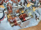
Edit: I was able to shoehorn the shield off of the FM tuner so at least I have access to test some points in there. Wow, is it cramped quarters in there! Now that the cover is off I might do some probing around tonight and tomorrow and see if anything interesting shows up.

Testing that diode in circuit with my multi-meter shows the forward bias as .555 V and reverse bias as being over limit.
 

Attachments

  • IMG_20240530_213643.jpg
    IMG_20240530_213643.jpg
    166.9 KB · Views: 9
Last edited:
I think that I'm on the right track finally!

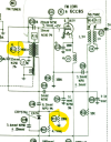
Checking resistors in the FM tuner in circuit yields two possible standouts.

According to the schematic R11 should read 3,900 ohms and it measures at 0.4!
R13 should measure 220k and reads 483k.

R15 should be 10k and is 11.18k
R14 should be 100k and is 104.1k
R12 should be 4.7m and is 4.9M

To me, these three seem acceptable, but I understand that RF and oscillators are a fickle thing.

I am thinking that there is a possibility of something in the circuit interfering with the measurement of R11 - as far as I know it is very rare to have resistors drift so low as to almost be a short. Tomorrow, I will carefully lift a leg on R11 and R13 and test. Thankfully neither of these are buried too deep into the tuner and are fairly easy to access.

1717129493394.png
 
if any of those stick out as a problem its R13 at more than double the value. Its part of a voltage divider so it might be enough to allow the AFC diode to be forward biased enough to just conduct rather than working as a variable capacitence. The others look to be within reasonable tolerances.

R11 is reading through the coil, so it will show as a near-short.

diode seems OK, if it was bad in some obvious way it would show a short or open in both directions. Open one way and about a half volt the other way seems reasonable. Its operating as a varactor, which is a voltage-controlled capacitor but all diodes do that to some degree and they will function test like a regular diode.
 
if any of those stick out as a problem its R13 at more than double the value. Its part of a voltage divider so it might be enough to allow the AFC diode to be forward biased enough to just conduct rather than working as a variable capacitence. The others look to be within reasonable tolerances.

R11 is reading through the coil, so it will show as a near-short.

diode seems OK, if it was bad in some obvious way it would show a short or open in both directions. Open one way and about a half volt the other way seems reasonable. Its operating as a varactor, which is a voltage-controlled capacitor but all diodes do that to some degree and they will function test like a regular diode.
Gah, no luck.

I went back and measured R13 before pulling it and it's measuring at exactly 220k - right where it should be. I must have clipped my probe onto the leg of something else in there last night and gotten a false reading.

On the bright side I have narrowed down a few more things that aren't the problem. I think today I will try and carefully take some voltage measurements in there and see if something stands out.
 
Back
Top Bottom