
• The move to the new server is done. There are some software and database maintenance updates in process. This has us passing the hat around to help out. We appreciate any donations. Seriously, even a dollar helps. The payment page may be found here - https://www.audiokarma.org/support.html

Western German Nordmende radio to amp conversion project

radex7

AK Member
I acquired a box of goodies to play with in my pursuit of tube fun. The donor was either a Nordmende Tannhauser radio or Arabella console. Included are: PT, 2x OT, Siemens and AEG Rectifier, and finally cute little pcb that hosts handful of resistors, capacitors,12AU7, 12AX7, and 2x 6BQ5. It was that board that won me over.

It looks like a mess, but is cleaning up nicely already.
IMG_3762.JPG
board_sch.jpg


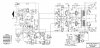
The plan is to get it going! Really! I am hoping to pretty much re-create the amp section of the unit and see what happens. If that proves impossible - than maybe RH84. What do you guys think of this design? Below is a slightly tweaked schematic of the radio:
rg_schem.jpg
 
Register to hide this ad
Thanks! I am still deciphering schematics,and making sense of pcb. Hopefully will not be to difficult.
 
I dig German stuff. Usually sounds pretty good. It usually sucks a bit to work on, but that actually doesn't seem too bad. Be careful with that PCB, early ones tend to lift traces, especially ones that got subjected to a lot of tube heat.
 
Well, I am moving along. Today I finish cleaning the pcb, mounted all of the components on a board, put my first two caps in, and bridged a couple of traces where pcb was chipped. Lets see some pictures:
 
Last edited:
Not sure why, but i get this:

Audiokarma Home Audio Stereo Discussion Forums - Error
You do not have permission to view media within this album.

can't see any of the pics.
 
Thank you, gadget! I didn't realize that my permissions were set that way! Please let me know if you can see them now.
 
I would reiterate a friendly warning by gadget regarding those trace lifts. I had this happen to me on a German radio repair and it was teeth-gnashingly frustrating to repair. Especially in a confined space. Be careful with soldering temperature and time spent with connections on those traces. If you apply too much heat or leave it for too long, that can cause further trace lifting in the circuit, in lieu of the original area of concern.

With a lot of the German stuff, this problem seems to be amplified as the valves are operating close to one another and the enclosure. This means everything in there is going to stay hotter and for longer periods of time, even after turned off.

Oh, and double check those German schematic symbols if in doubt. They threw me for a loop the first time I analysed a few! Good luck, that looks like a nice piece of gear!
 
+1

Careful with the PCB's, I had to bridge some of mine with wires because I applied too much heat.

BTW, my Nordmende Menuett is a great performer and it has a gorgeous look.

Patrice
 
I made some progress! I am still, however, in sorting things out stage. Something came up that I would like to ask about here. The output transformer is designed to work with multiple input voltages, 110, 130 (or 125 per label), 150, 220, and 240. I tested the output with both 110 and 130 volts selected, and I got interesting results. When 110 was selected, the "small" outputs (6.3V and 3.15V) were spot on, but what was supposed to be 210V output was actually 240V (I think), will check again later. When I switched to 125/130V input, small output voltages dropped to roughly 6 and 3, but the "big" one was spot on at 210V. Does this make sense? Any experience with that?

Second question/situation. Rotten eggs. Oh you know, the rectifier. So my package consisted of the flat Siemens can that is the rectifier, but there is also the black AEG can, that is not a capacitor. In the schematics they just appear as a rectifier. How are they normally installed/connected? What is the purpose of the black can then? Sketches appreciated ;-)

Last but not least, the output to speakers, and the whole right side of the schematic. The back panel has a tap for a third loudspeaker. How can I simplify this to a single/simple output?

More questions to follow! ;-)

Thank you!
 
It will read high if you have no load on it. I'd get the heaters right and worry about the HV later. If its too high, you can drop it easily with a resistor.

Normally you get the flat pack rectifier or the can type rectifier. Can't say I've seen both unless it has two HV supplies. The flat packs are relatively obvious, there should be 3 or 4 terminals. The two with ~ markings are AC in, + is positive out, and if it has a fourth terminal you have a - out as well. If no fourth terminal, the case is grounded and it just connects through the mounting screws. The round cans work pretty much the same way, though I will admit to not being familiar with what exactly they used for markings.


Off topic, but if you aren't using that original power switch, might I talk you out of it? One of my German radios uses that switch with the notch in the paddle, and mine is dead. I could probably make one out of a regular switch but my laziness would love to snatch one on the way to the trash first.
 
Cool stuff.

When I have a PCB subject to heat, I use tube saver to raise the tubes, therefore a lot less heat gets radiated on the component near by and the PCB itself.
No sound difference.
 
Gadget, pm me about that switch, I have no attachment to it...
While I was gathering courage to place a big parts order for caps and such, I came across this little gem! This is a design by Norman H. Crowhurst (1957), featured in a cool article about twin coupled amplifier. The design was so similar to my Tanner that I just had to bring it up!

crowhurst_amp.jpg

Additionally, qustions about voltage rectifications were addressed in this awesome youtube video:
It is still not clear to me what capacitors should be used in the design, but there seem to be some wiggle room.

 
that is a bizzare output stage, driving dual transformers, one from the plate and one from the cathode. I've seen cathode feedback windings on transformers before but never anything like that. Looks a bit like they're trying for a Unity coupled design akin to a McIntosh without actually having the Mc transformers. Wonder how well that works out in terms of performance and stability.


Anyway, I'd probably go for something around 100uf at 450 volts for your amp, at least for the first stage. Solid state rectifiers can handle more cap than tube ones will deal with, and you'll get better filtering as well. You can downsize it a bit after that if you want, 47uf would likely be fine.
 
Current state of affairs: found some 1n4007 diodes for my rectification needs. Realized that flat can Siemens did not belong in the parts assortment. Also put together a list of capacitors I need to get.

Ready for another question?

I poked around tubesandmore site and picked a bunch of dijons, adding up to $70 just for this project. Kinda costly! I then found on justradios some capacitor kits that offer way more caps for little more money. Anyone has an experience with those bundles? What brands can I expect in there? Worth the shot? Where do you get your supplies from? Thanks!

​
 
I've used a number of their cap kits. Its the same yellow caps I buy elsewhere in larger quantity. I haven't had any bad ones, so by that standard I think they work fine.

Can't recall the brand, but its not Illinois. Its something with 3 letters, ETR, something like that. I think the 100 bag lots I've gotten them in say that they are made in Taiwan.

I get mine from oldradioparts.net. Faster shipping since its within the US. I had a package lost coming out of Canada, and shipping from there isn't the cheapest. One thing you will likely find with the kits is that you get some values that you just won't make much use of. I still have some out of the assortment I bought years ago, and other values I've re-stocked a couple times now. Stuff from 0.01uf through 0.22 get used a lot, smaller values not so much. They are nice to have on hand when you run into an oddball need though.
 
This is a design by Norman H. Crowhurst (1957), featured in a cool article about twin coupled amplifier.
Not sure there is any similarity between the Arabella and the Crowhurst design - Arabella has single-ended output stages, while the Crowhust design is push-pull.
 
Can't recall the brand, but its not Illinois. Its something with 3 letters, ETR, something like that. I think the 100 bag lots I've gotten them in say that they are made in Taiwan.

apparently I'm losing it entirely. The big bags of cheapie yellows I got last time are Richey brand. Maybe something I had gotten previously had the letters.
 
Back
Top Bottom