
• The move to the new server is done. There are some software and database maintenance updates in process. This has us passing the hat around to help out. We appreciate any donations. Seriously, even a dollar helps. The payment page may be found here - https://www.audiokarma.org/support.html

What am I missing testing bridge rectifiers?

oldNslo

Active Member
I surely watched more than 3 YT vids on testing these 4 pronged buggers, and paid close attention, putting my pizza down while watching, but somehow I got on the wrong school bus. Where I thought that each pair was to have a small AC voltage (applied from the MM lead), each and every combination should have an OL and .51 (example) reading to validate it's good. Ok, some can go higher, and they do approach .99vac, for both old and new. My Fluke even beeps if it's good (how can I go wrong?) I then ordered 2, because both OLD ones in the power supply measured OL/OL on the AC legs. Easy peasy, right? The new Digikey replacements measure (close enough) to my 2 old ones, meaning OL/OL on the AC legs as well. My neighbors nearly called 911 with the sounds emanating from my garage.

Where did I go wrong? Don't hold back, I'm learning.

Pic shown, has new on the left, old on the right. Both with AC legs oriented on the bottom. DB105 is the part #. DB105.JPG
 
Register to hide this ad
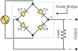
Such diode bridges are just 4 diodes connected, eg, attached pix sourced from net.

Testing bridges involves testing the individual diodes eg,
with red probe on top AC and black on red + sign expect 0.6V, reverse the polarity and get OL.

Also with red probe on red - sign(AC) and black on + sign(AC) expect xxV ie, path through D3, D1 or D2, D4.
Reverse polarity and get OL.

Important to refer back to the pix to see what you are testing.
 

Attachments

  • diode_bridge.png
    diode_bridge.png
    10 KB · Views: 3
If you measure between the AC inputs, you SHOULD get OL/open as one diode will pass current but the other will block current either way. You need to measure each diode individually.

Doug
 
  • Like
Reactions: mbz
Thanks all, I had thought I was doing the test the proper way. This vid cleared it up for me (cued to the relevant section):

The vid also cleared up my double voltage reading at min 8:16.

Thanks @mbz for again being first to the net with the clarity. I continue to be thankful.
 
Back
Top Bottom