• The move to the new server is done. There are some software and database maintenance updates in process. This has us passing the hat around to help out. We appreciate any donations. Seriously, even a dollar helps. The payment page may be found here - https://www.audiokarma.org/support.html

what are your feelings about chinese 5AR4 tubes

I've run a Chinese 5AR4 in a refurbed Dyna 70 with no problems, using the enhanced yellow sheet mod, the larger capacity quad cap (40/80/30/20), and surge supressors on the power transformer primary. All, imo, common sense measures.

Whats the first cap off the rectifier? Up to about 40uf is fine but many of the replacement cans have an 80uf section. It won't be happy trying to charge that up.

I am confused. Two very highly respected contributors here seem to have opposing perspectives on this. I guess my more specific question relates to how PIO was able to get away with caps of those values. I had believed that the stock can values are at the edge of the circuit's capabilities. Could I just put a 40/80/30/20 can in my ST70?
 
I have that can in mine but made the mistake of putting the 80uf after the rectifier. The Sovtek lasted about a week before developing a bad hum. After installing it correctly with the 40uf at the rectifier and doing the yellow sheet mod and replacing that tube there have been no problems, although I replaced the rectifier at the year and a half mark as a precaution. They are cheap enough. Wasn’t the stock value 40uf at the rectifier?
 
Most all of the OLD STOCK DATA Sheet's for 5AR4's list 60uf for Capacitor input (1st section or cap right off the tube.). Haven't seen one for the Russian and Chinese tube, but presume they copied the spec's. The 40/80/30/20uf cap is fine with the 40uf as 1st section. The Russian and Chinese tubes aren't as robust as OLD STOCK 5AR4's, and having said that I'd run them at NMT 40uf along with the Yellow paper mod. OR get a Solid state rectifier (You could make one also with a base and a couple of diodes.).
 
What I gather after reading many posts on chinese tubes is that its a crap shoot and new 5ar4s are not as robust as they used to be. Guess thats why the old ones sell for more than many output tubes.

Edit, See Larry confirmed what I suspected while I was typing.
 
I am confused. Two very highly respected contributors here seem to have opposing perspectives on this. I guess my more specific question relates to how PIO was able to get away with caps of those values. I had believed that the stock can values are at the edge of the circuit's capabilities. Could I just put a 40/80/30/20 can in my ST70?

I've used a 40/80/30/20 but I connected the 40uf section directly to the rectifier. Pretty sure the instructions that come with the can say to do that as well. Just making sure thats what was actually done. If the 80 was connected straight off the rectifier, it gives it a much rougher life.
 
I am confused. Two very highly respected contributors here seem to have opposing perspectives on this. I guess my more specific question relates to how PIO was able to get away with caps of those values. I had believed that the stock can values are at the edge of the circuit's capabilities. Could I just put a 40/80/30/20 can in my ST70?
I installed it to work in the order listed. 40 uF from the rectifier to the choke, 80uF from the choke, 30 uF next, then 20 uF. The tube can handle 40uF direct, not 80uF. With the enhanced yellow sheet mod, the tube acts as a doubled series resistance warm-up delay element within its specification.
 
Last edited:
The TAD red base units are fine. I used some recently in a pair of MK IIIs that I rebuilt and they survived my 24 hour burn-in test. However, I also always put solid state protection diodes on the sockets (1500V-rated, not UF4007/1N4007s) in case the vacuum rectifier croaks. 1000V rating of the *4007 isn't sufficient for the voltages present on the ST-70, so you'll either need 2 in-series with parallel caps to ensure proper load-sharing (Merlin has a good explainer here: http://www.valvewizard.co.uk/bridge.html -- look for "Two-Phase Rectifier"). Anyway, I keep a small inventory of 1500V 2A diodes around so that I don't have to bother.

Thorpej:

I have UF4007s installed in my MKIIIs, but not two in series. I like the idea of using a higher rated diode and will go this route when I rebuild my ST-70, and maybe go back and retrofit the MKIIIs. A check on Mouser led me to a BY448, which is 1500V, 2A in an SOD-57 case, is this what you use?
 
I don't use Chinese tubes of any type. Have you done the 5AR4 yellow sheet mod to this ST-70? That's essential for most modern 5AR4s. Also, don't be tempted to plug in a SS replacement without considering all the potential problems. Doing this properly really requires adding a time delay so that B+ doesn't come up before all the tubes are conducting.

Jack

5AR4 Yellow Sheet Mod.jpg
 
I've used a 40/80/30/20 but I connected the 40uf section directly to the rectifier. Pretty sure the instructions that come with the can say to do that as well. Just making sure thats what was actually done. If the 80 was connected straight off the rectifier, it gives it a much rougher life.

40mFd in first filter section is fine for the GZ34/5AR4. :thumbsup:
 
The last time I was using Chinese 5AR4/GZ34's regularly was back in the 1980's & 90's, as it was darned near impossible to find anything else at the time, especially in the pre-intergooglewebnet days.

My experience was that it was a bit of a crapshoot; rectifier or flashbulb? flip a coin...Mind, if you got a good one, they were virtually impossible to kill. They all had brown bases with arc-ribs between the pins, iirc.
 
I don't use Chinese tubes of any type. Have you done the 5AR4 yellow sheet mod to this ST-70? That's essential for most modern 5AR4s. Also, don't be tempted to plug in a SS replacement without considering all the potential problems. Doing this properly really requires adding a time delay so that B+ doesn't come up before all the tubes are conducting.

Jack

View attachment 2563473

^^ This
It adds some silicon diodes in series with the rectifier tube to stop flash over.

I do not like the SS replacement, even with a dropping resistor, as the B+ is immediately high before the tubes have heated up putting stress on the capacitors and the tubes. You'll shorten the life of both.
 
True. There are small slow ramp up B+ boards available though. I've seen a few for sale. They give a slow ramp up of the B+ after the heaters have warmed up. Not like the simple delay boards like what VTA sells.
 
Rate your caps appropriately, its really not that big of a deal. Plenty of gear was made with solid state power supplies in the tube era and none of it seemed to be overly inclined to eat tubes or blow up capacitors because of it.

or I guess maybe I should encourage this sort of fretting. Send all those garbage Citation II and Fisher and other trash amplifiers to me for disposal, replace them with some nice reliable amplifiers that eat expensive rectifier tubes like candy.
 
How do you measure inrush? I've put volt meters across secondaries and even after each cap in the power supply and have yet to see big swings in voltage at startup. With SS or tube recrifiers.
 
Which circuit do you have the most concern for? PT primary, total current? Heater circuit? HT/SS rectifier/B+ circuit?
No concerns. I just haven't personally observed these big inrushes of voltage or even current that some have spoken of with any of the equipment I have.
So I thought maybe I was doing something wrong when measuring.
 
How do you measure inrush? I've put volt meters across secondaries and even after each cap in the power supply and have yet to see big swings in voltage at startup. With SS or tube recrifiers.
If that's true, then you're not measuring those SS supplies from cold. The output voltage must sag when the the tubes warm up and conduct. The drop is a function of the series resistance through the PS. And contrary to what's been said about this being no big deal, there are issues other than just the voltage ratings of all the caps. Direct-coupled phase splitters like the one below (also applicable to cathodynes) rely on the B+ delay to prevent damage. Without the delay, full B+ will be applied between the grid and cathode of the second tube until the first tube conducts. Some tube types can handle this; some can't.

DC LTP.jpg

Jack
 
Iirc, inrush current surge can be a solid state rectification charging elyticaps, and /or the magnetic state of the PT core vs phase on turn-on. The last can produce an audible thump from the PT with the current surge thru the primary.
 
^^ This
It adds some silicon diodes in series with the rectifier tube to stop flash over.

I do not like the SS replacement, even with a dropping resistor, as the B+ is immediately high before the tubes have heated up putting stress on the capacitors and the tubes. You'll shorten the life of both.
When I build things I prefer to use tube rectifiers that are indirectly heated so the voltage ramps up slowly.

But I also have vintage gear that uses directly heated tube rectifiers and SS rectification and I've never worried much about it. I figure if it's survived this long without it causing any damage then I shouldn't be too concerned. I do sometimes add a thermistor, though.

One thing I plan to try on my next build is a design that Eli Duttman, who posts over at AA and DIY Audio, has discussed many times over the years. It's called a Cockeyed Bridge.

He originally suggested it, many years ago, as a way to reduce the cost of building a SS power supply that used high voltage Cree Silicon Schottky diodes which, as I recall, may have been considerably more expensive than they are now. (??) The design allows you to use cheaper UF4007s and only a single Cree SiC, thereby saving a bit.

The same design can, however, also use a tube in place of the Cree SiC, which is the implementation that interested me.

I drew a schematic using a common 6AX4GTB damper diode which provides the soft start.
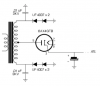
Cockeyed Bridge with 6AX4GTB .png
I've never used this tube before but I believe it ramps up the voltage at least as slowly as the 5AR4, and maybe even slower. If you've ever bought a box of old TV tubes there are likely a few in there. If not, they're super cheap, the dealer near me sells them for $4.

This particular design, using the 6AX4, couldn't be used in an ST70 because it can't handle as much current as a 5AR4. Perhaps there are other damper diodes that can handle more current, I don't know. If not, in a DIY build, I suppose you could use a pair of them if you needed to supply more current.

Maybe I'm wrong, but it looks to me like it's essentially the same, electrically, as the "yellow sheet mod", it's just configured differently. I see it mainly as a way to get slow start cheaply.

 

Attachments

Iirc, inrush current surge can be a solid state rectification charging elyticaps, and /or the magnetic state of the PT core vs phase on turn-on. The last can produce an audible thump from the PT with the current surge thru the primary.
The phasing issue can be significant. I have a high current DC supply in the garage that I use to operate various machinery. The transformer is huge, and I believe it originally came from a 13.8V 50A supply. If I turn it on at the wrong time (relative to the phase of the AC mains), the transformer "thumps" and blows the dedicated 15A breaker. A solid state relay with a zero-cross function can eliminate this issue, but I'm not sure they're suitable for use near high-gain audio gear.

Another option is to use a conventional 120VAC relay with its coil connected in parallel across the transformer primary. When the amplifier is first turned on, the HV transformer is powered through a resistor, dropping the voltage. As the caps charge and current decreases, the voltage drop across the resistor decreases, and the voltage across the primary increases. Eventually, the increasing voltage energizes the relay, and its contacts short the dropping resistor, delivering full voltage to the transformer. This prevents the large current surge that would otherwise result from energizing the primary winding initially with full voltage.

Jack
 
Last edited:
That's well past the inrush surge period, which is the 1st .1 sec after power on, for the SS B+ filter charging. ..and the bias supply filter, if equipped.
My reply was concerning the voltage surge, not current. I was responding to post #36, where Lavane mentioned measuring the voltage.

Jack
 
Back
Top Bottom