• The move to the new server is done. There are some software and database maintenance updates in process. This has us passing the hat around to help out. We appreciate any donations. Seriously, even a dollar helps. The payment page may be found here - https://www.audiokarma.org/support.html

What to do with H/K TA-260 output transformers

thorpej

AK Subscriber
Subscriber
I recently picked up a pair of output transformers from a H/K TA-260... 4K CT, with 4, 8 and 16 ohm secondaries. This model used 7355s and was probably in the 30W/ch ballpark.

One option would be to make an EL34 amp out of them.

But I also have a bunch of 6080s, and was thinking that since they're dual triodes, a single-bottle-per-channel push-pull amplifier might be fun. I drew up an AB1 operating point that has 230V across the tube and biases at about -130V. Because the data sheet recommends not using fixed bias, I'd want probably a 370V B+ rail (to get 360V to the plates, after resistive losses in the OT), and then a 3K 10W resistor on each cathode. I think I could get 15W/ch (conservatively) out of that, but I'm mildly concerned about using cathode bias with an AB1 output stage (and the bias shift that would occur in the Class B portion of the load line).

Needs a lot of driving voltage, but a Mullard 5-20 type front end using 12AX7s should be up to the task -- the 6080 can easily handle a 470K grid circuit resistance (1M ohm is listed as the max in the data sheet).

Anybody here built a 6080 output stage?
 
Register to hide this ad
7355 would be pretty equivalent to a 5881 but a 4k load seems a bit on the low side there.

I wonder if the 6080 no fixed bias thing is related to it's intended use as a power supply pass element. The datasheet I found says this

"With fixed bias the anode circuit should contain a protective resistance to
provide a minimum drop of 15 V d.c. at the normal operating conditions.
When two or more sections are used in parallel at dissipations approaching
the rated maximum, separate anode and cathode resistors must be used to
assist load sharing.
When combined fixed and automatic bias is used, the cathode bias portion
should have a minimum value of 7.5 V d .c . at the normal operating condi -
tions. Rg should then not exceed 100 k Ω."

https://frank.pocnet.net/sheets/009/6/6080.pdf

the source link says its a Phillips datasheet, and it has the look.

Sounds like you can mix it rather than using such a massive cathode resistor. That would significantly limit how much your bias point changes.

If a Mullard-style front end won't get it done you could stab a cathode follower (or functional equivalent with MOSFET or whatever) between the inverter and the output tube grids.
 
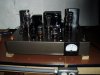
I built one last year,,, well, 6AS7PP,,, used a pair of Pioneer OPTs... Built the adjustable (about 10V) cathode circuit to balance the triodes, with Gadgets help... very nice sounding amp....
 

Attachments

  • P6170054.JPG
    P6170054.JPG
    78.9 KB · Views: 26
  • P6230068.JPG
    P6230068.JPG
    86.1 KB · Views: 27
I built one last year,,, well, 6AS7PP,,, used a pair of Pioneer OPTs... Built the adjustable (about 10V) cathode circuit to balance the triodes, with Gadgets help... very nice sounding amp....

What does the power supply look like? Can't quite read what the B+ says. And it looks like you're using a 5K CT output transformer? How much power do you get out of it?
 
If a Mullard-style front end won't get it done you could stab a cathode follower (or functional equivalent with MOSFET or whatever) between the inverter and the output tube grids.

Yah, I've been thinking about essentially always using a MOSFET source follower from now on in all of my driver stages ... the input impedance of a power MOSFET is so high that you don't have to bother computing the AC load line, and the extra parts are all of $10 (for a stereo push-pull amp).
 
I would suggest using 6B4G'S , If the tube sockets are wired correctly , EL34's and 5881 could also be used by just adjusting the bias .
 
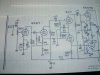
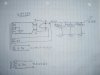
OPT is 5K Pioneer,,, output is 15W or so, IIRC... Here's the original schem and my PS, there is a 5uF oil cap right after the rectifier, 5U4GB,,, choke is Triad C-40X...
 

Attachments

  • P5280001.JPG
    P5280001.JPG
    55.9 KB · Views: 16
  • P8070056 (2).JPG
    P8070056 (2).JPG
    83.9 KB · Views: 15
Last edited:
maybe 6P15P / SV83 if you're going close to that route. Cheaper, little bit less common, and they actually work well if you keep things at sane levels. I'm listening to something I cobbled from assorted bits that runs them. It does a solid 11 per channel. I might be able to get an extra watt or so out of an EL84 but I doubt it would do much more than that. Idles at 11ma per tube for lowest distortion with EFB, thats absolutely paltry amounts of current.
 
OPT is 5K Pioneer,,, output is 15W or so, IIRC... Here's the original schem and my PS, there is a 5uF oil cap right after the rectifier, 5U4GB,,, choke is Triad C-40X...

Hm, nifty. I have a small stash of 6A6s (6N7s in a 7-pin base with ST-14 bottle) that would visually fit the bill with 6AS7Gs (which I also have a small stash of).

No feedback, huh?
 
Nope, no FB,,, I found the schem on line, after an audio show that provided some NOS 6AS7Gs for pennies,,, was told they are only voltage regulators, no good for audio!!! Glad I wanted to see for myself!!! The schem is Japanese, I believe from 1956... I'm sure,with your design skills you'll come up with something pretty cool... Glad Gadget let me pick his brain,, the bias/balancing circuit makes it work... These tubes are not supposed to have real closely matching sections, but with an adjustment pot on each triode, they dial in right on the money, and seem to hold steady, about 89-90VDC... I used NOS AB pots for dialing them in....
I typically use it with OLA speakers, and it rocks them pretty well... My build thread is on here someplace, if want to see it,,,

Here's a thread,,, http://audiokarma.org/forums/index.php?threads/6as7g-pp-amp-balance-circuit.703852/
 
Last edited:
OPT is 5K Pioneer,,, output is 15W or so, IIRC... Here's the original schem and my PS, there is a 5uF oil cap right after the rectifier, 5U4GB,,, choke is Triad C-40X...

Ok, if you're using a 275V B+ rail and it biases up at +90V on the cathodes, then it's 185V across the tube, and 90V across 1425 ohms is 62mA, so that makes sense against the plate characteristics graph. Looks to me like it's Class A all the way (or, at least, if it ever did enter Class B, the cut-off point would be about the same), and pretty non-linear -- eyeballed, maybe 40% less voltage swing on the negative portion of the input signal than the positive portion... but all of that non-linearity probably doesn't matter because it's push-pull so all of the even harmonics are disappearing in a puff of greasy smoke (err, I mean, the output transformer) anyway.

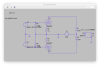
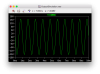
I threw together a quick simulation assuming an ideal 4KCT->8 ohm transformer (i.e. modeled only the impedance ratio using an arbitrary primary inductance of 10H per half the winding - which is 40H across the whole winding ... 40H / (4000 / 8) = 80mH secondary inductance). Driven to full power (180Vpp input signal), that arrangement would give me about 10W.

But if I used 225V for B+ and biased at -120V, then driven to full power (240Vpp input signal) that would give me 14.8W as Class AB1. In this arrangement, both load lines are below the max dissipation curve. For audio service, I wonder if it would be a problem going above the max dissipation curve in the Class B portion of the load line.

That needs 85Vrms of driving voltage, which for my usual target of 500mVrms input sensivity, requires 44dB (170x) of gain. Yikes :-) That's a tall order for an all-triode 5-20-type front end, even without NFB.
 

Attachments

  • Screen Shot 2017-10-29 at 4.09.10 PM.png
    Screen Shot 2017-10-29 at 4.09.10 PM.png
    143.7 KB · Views: 7
  • Screen Shot 2017-10-29 at 4.09.13 PM.png
    Screen Shot 2017-10-29 at 4.09.13 PM.png
    69.2 KB · Views: 6
Last edited:
That needs 85Vrms of driving voltage, which for my usual target of 500mVrms input sensivity, requires 44dB (170x) of gain. Yikes :) That's a tall order for an all-triode 5-20-type front end, even without NFB.

By which I mean "Oh, no, actually that should be no problem." Math is hard sometimes.
 
Back
Top Bottom